BLOWER WIRING CONNECTIONS
A WARNING: DISCONNECT
FURNACE ELECTRICAL POWER
BEFORE ATTEMPTING TO
CHANGE THE BLOWER MOTOR
SPEEDS. FAILURE TO DO SO MAY
DAMAGE THE EQUIPMENT AND
CAUSE PERSONAL INJURY OR
DEATH.
UTEC, Honeywell and Johnson
Controls
The furnace control board comes
wired with the
heating speed tap
connected to the terminal marked
"HEAT" and cooling speed tap
connected to the terminal marked
"COOL".
Any unused motor speed
taps connect to terminals marked
"M1" and "M2."
The motor speed taps may be
changed to fit the needs of a specific
installation.
Reconnect any unused
motor leads to terminals "M1" and
"M2."
Check the motor speed tap
wire color for the specific speed as
marked on the wiring diagram.
These controls have two additional
fan motor terminals, marked "FAN"
and "HEAT/COOL."
The terminal
marked "FAN" is for constant
blower operation.
The low speed
motor tap is connected to the
"FAN" terminal at the factory.
The thermostat fan switch must be
set to the "ON" position for constant
fan operation.
If the installation only needs one
fan speed for both heating and
cooling, attach the one
appropriate speed tap to this
"HEAT/COOL" terminal.
Anytime
the unit calls for blower operation
in either heating or cooling, it
automatically operates this one
speed.
IMPORTANT: DO NOT ATTACH
ANY MOTOR SPEED TAPS TO
EITHER OF THE "HEAT" OR
"COOL" TERMINALS, IF USING
THE ONE SPEED "HEAT/COOL"
TERMINAL. SERIOUS MOTOR
DAMAGE RESULTS.
NOTE: "J" series furnaces DO NOT
HAVE
the "HEAT/COOL," "FAN," or
"M2" terminals on the UTEC 1012-
925 control.
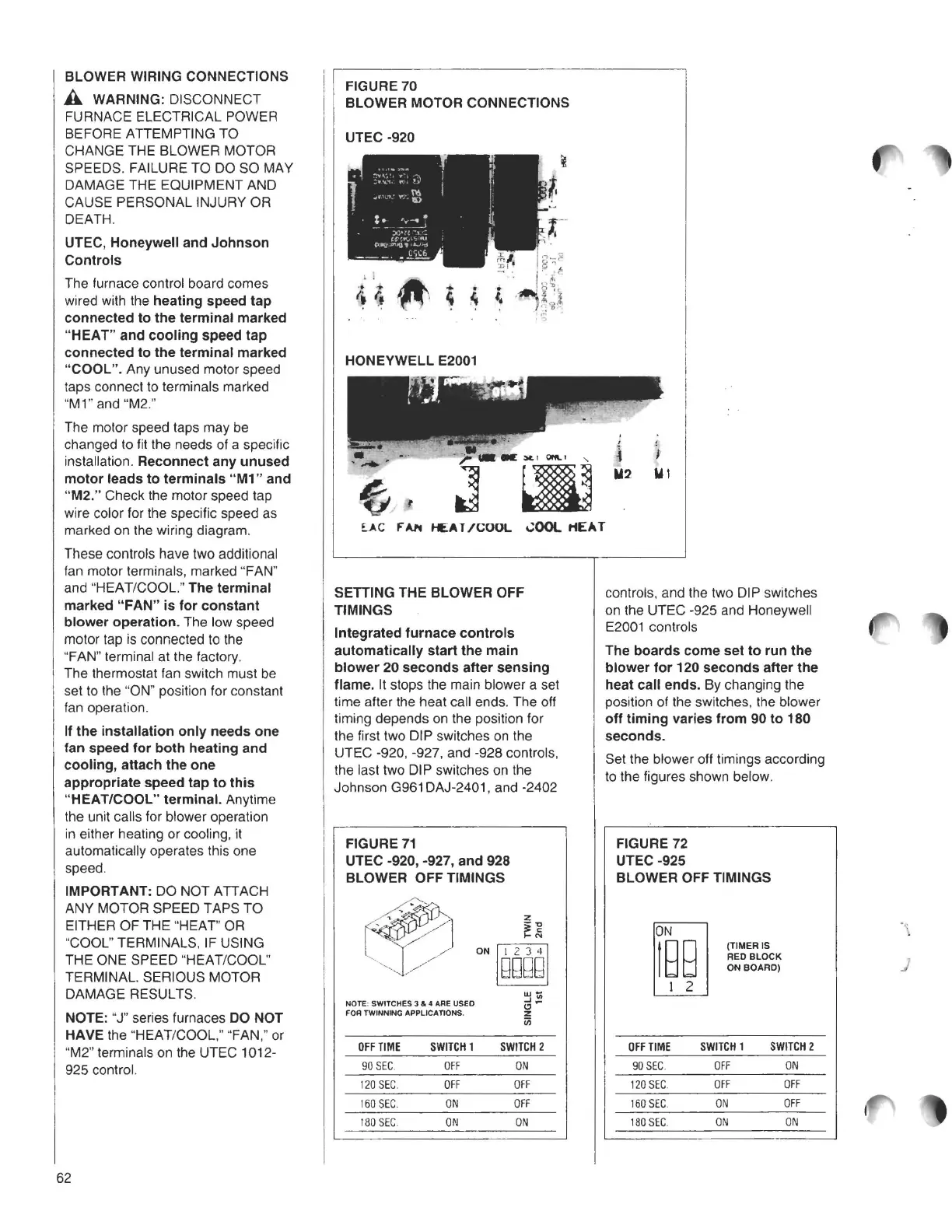
FIGURE 70
BLOWER MOTOR CONNECTIONS
UTEC -920
HONEYWELL E2001
4
,
I
M2 M1
U.C FAN HEAT /COOL ~OOl ttEA T
iii
OFFTIME
90 SEC.
120 SEC.
160 SEC.
I 80 SEC.
SWITCH
1
OFF
OFF
ON
ON
SWITCH2
ON
OFF
OFF
ON
SETTING THE BLOWER OFF
TIMINGS
Integrated furnace controls
automatically start the main
blower 20 seconds after sensing
flame.
It stops the main blower a set
time after the heat call ends. The off
timing depends on the position for
the first two DIP switches on the
UTEC -920, -927, and -928 controls,
the last two DIP switches on the
Johnson G961 DAJ-2401, and -2402
FIGURE 71
UTEC -920, -927, and 928
BLOWER OFF TIMINGS
!~
~
z
/
.
ON /ggggj
w-
..I"'
NOTE, SWITCHES 3 & 4 ARE USED
C,
~
FOR TWINNING APPLICATIONS.
z
controls, and the two DIP switches
on the UTEC -925 and Honeywell
E2001 controls
The boards come set to run the
blower for 120 seconds after the
heat call ends.
By changing the
position of the switches, the blower
off timing varies from 90 to 180
seconds.
Set the blower off timings according
to the figures shown below.
FIGURE 72
UTEC-925
BLOWER OFF TIMINGS
(TIMER IS
RED BLOCK
ON BOARD)
OFF TIME
SWITCH1 SWITCH2
90 SEC. OFF
ON
120 SEC
OFF OFF
160 SEC. ON
OFF
180 SEC. ON ON
j
62