!9
'\I
..,
..
...
lUIN
2N)
FURNACETWINNING
A maximum of two furnaces may be
installed side by side on a common
duct system and operate as one. or
as first stage and second stage. The
twinning procedure makes both
furnace blowers operate together,
whether one or both furnaces are
firing. One thermostat can control
both units. This is necessary if the
two furnaces supply air for one 7-1/2
or 10 ton single stage cooling
system.
To twin two furnaces. follow these
instructions and the twinning wiring
diagrams at the end of the service
manual.
NOTE: Only twin furnaces with
identical controls from the same
manufacturer of control board.
►
NOTE: The "OK" LED flashes if
the twinning is not installed
properly. Hot Surface Ignition
control boards flash the "OK" LED
continually if twinning is not installed
properly. Direct Spark Ignition control
boards flash the "OK" LED five (5)
times, pause, and then flash five
times again.
NOTE:
"J" series units using the
UTEC 1012-925 control require the
RXGP-F03 twinning kit. This includes
extra door switches and wiring for
proper blower operation.
HONEYWELL S9201 E2001 IFC
BOARD TWINNING INSTRUCTIONS
1. Single Stage Wiring
a. Connect furnace "ONE" IFC
to the thermostat.
b. Remove the metal jumper
from the "XMIT" and ''RCV"
terminals.
c. Connect a low voltage wire
from "XMIT" terminal on
FIGURE 79
HONEYWELL TWINNING
CONNECTIONS
control IFC "ONE" to "RCV"
terminal on furnace IFC
"TWO".
d. Connect a low voltage wire
from "RCV" terminal on
furnace IFC "ONE" to "XMIT"
on furnace IFC ''TWO".
e. Connect the "GND" terminals
of both IFC boards together
with a low voltage wire.
f. Connect the "W" terminals of
both IFC boards together with
a low voltage wire.
2. Two Stage Wiring
a. Repeat steps a, b, c, d, and e
from above.
b. Connect thermostat terminal
"W1" to the "W" terminal on
furnace "ONE" IFC board.
c. Connect thermostat terminal
"W2" to the "W" terminal on
furnace "TWO" IFC board.
UTEC 1012-920, 1028-927 and -928
IFC BOARD TWINNING INSTRUC-
TIONS
1. Single Stage Wiring
a. Ensure that both furnace 24
volt power supplies are in
phase.
b. Connect furnace "ONE"
control board to the
thermostat.
c. Connect control board
terminals "C" to "C", "W" to
"W", and "TWIN" to "TWIN."
d. Set DIP switch "3" to the
''TWIN" position on both
control boards.
e. Set both furnace control
board DIP switches #4 to
the "1st" position.
FIGURE 80
UTEC SINGLE STAGE
TWINNING
..
0
z
..
en
~
....
~
.... 0
...-
-
I
-
.r-
II ;
....
"'
2.
Two Stage Wiring
a. Ensure that both furnace 24
volt power supplies are in
phase.
b. Connect furnace "ONE"
control board terminal "W" to
the "W1" terminal on the
thermostat.
C.
Connect furnace "TWO"
control board terminal "W" to
the "W2" terminal on the
thermostat.
d. Connect control board
terminals "C" to "C" and
"TWIN" to "TWIN."
e.
Set DIP switch "3" to the
"ON" position ·on both
furnace control boards.
f. Set furnace control board
DIP switch #4 to the "1st"
position on furnace "ONE".
g. Set furnace control board
DIP switch #4 to the "2nd"
position on furnace "TWO".
h.
Set the thermostat heat
anticipator for 0.1 amps on
each stage of heat.
►
NOTE: The UTEC 1028-927
and -928 controls use only
switch #3 for twinning.
Connect the thermostat to the
furnace intended to be first
stage. The other furnace
automatically becomes
second stage.
C
-
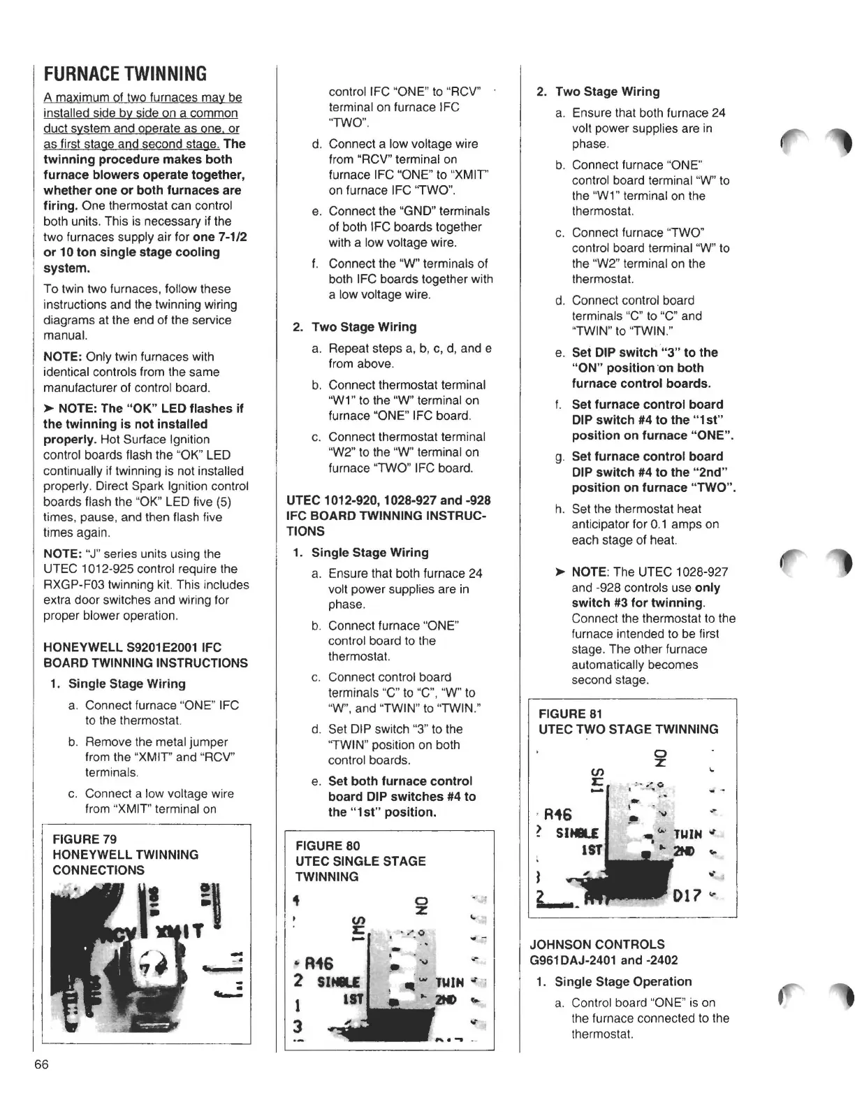
FIGURE 81
UTEC TWO STAGE TWINNING
0
z
en
...
JOHNSON CONTROLS
G961 DAJ-2401 and -2402
1. Single Stage Operation
a. Control board "ONE" is on
the furnace connected to the
thermostat.
66