UPFLOW UNIT RETURN AIR
Construct a bottom return air system
to come up through the floor under
the furnace with a direct connection
made to the bottom of the furnace,
For installations where return air
'
""
ducts cannot run under the floor,
connect the return air duct to the side
or rear as required. Side or rear
return air cabinets are available from
the manufacturer.
If side, or rear, air return is used,
determine the opening size required
and mark a line between the
knockout squares. Cut an opening
along these lines.
NOTE: Ensure that any loose pieces
of insulation are removed from the
blower compartment. Do not allow
any insulation pieces to be drawn
into the blower wheel.
IMPORTANT:WHERE THE
MAXIMUM AIR FLOW IS 1800 CFM
OR MORE, BOTH SIDES OR THE
BOTTOM MUST BE USED FOR
RETURN AIR.
A WARNING:THE SOLID METAL
,
,.,
BASE PLATE MUST BE IN PLACE
WHEN THE FURNACE IS
INSTALLED WITH SIDE OR REAR
RETURN AIR DUCTS. REMOVING
THE BASE PLATE COULD CAUSE
PRODUCTS OF COMBUSTION TO
CIRCULATE INTO THE LIVING
SPACE CREATING POTENTIALLY
HAZARDOUS CONDITIONS,
INCLUDING CARBON MONOXIDE
POISONING.
NOTE:
Install upflow units in the
upf!ow position only.
A WARNING:NEVER OPERATE
THE BLOWER OR BURNERS
WITHOUT THE BLOWER DOOR IN
PLACE. FLUE GAS CAN BE
DRAWN INTO THE LIVING AREAS
POSSIBLY RESULTING IN
CARBON MONOXIDE POISONING,
PERSONAL INJURY OR DEATH.
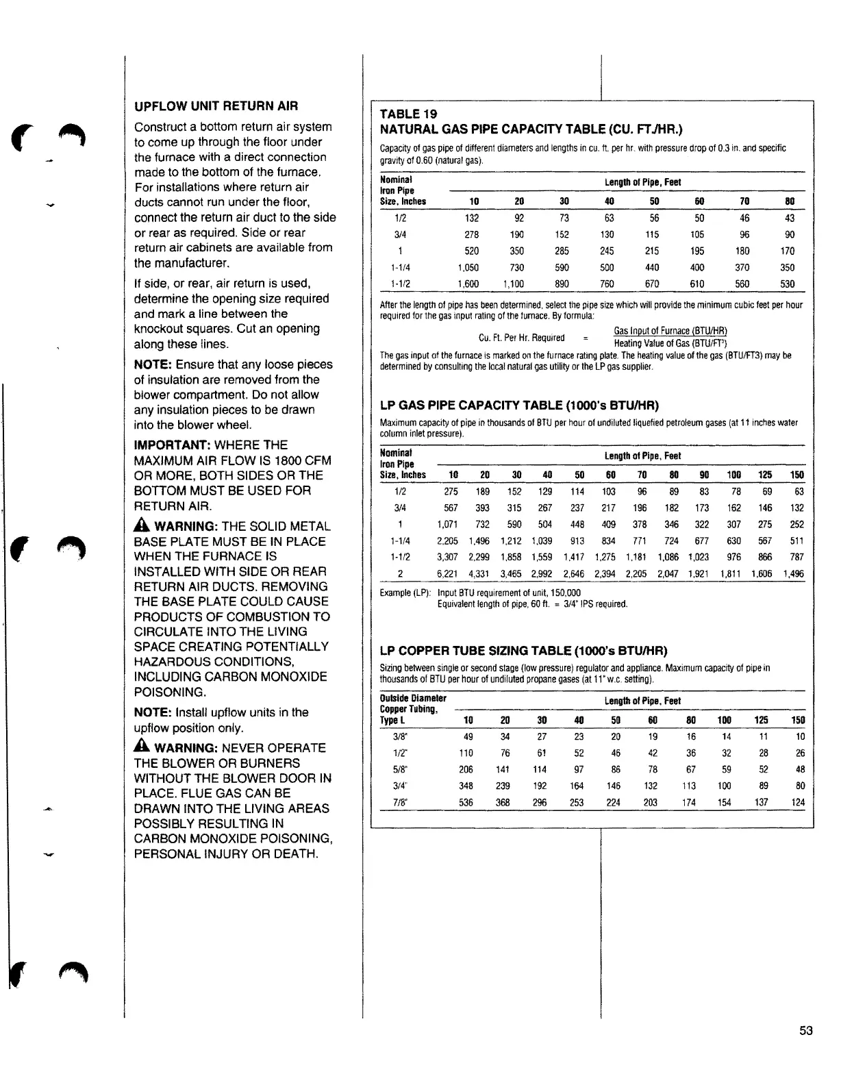
TABLE19
NATURAL GAS PIPE CAPACITY TABLE (CU. FT JHR.)
Capacityof gas pipe of different diametersand lengths in cu, ft per hr. with pressure drop of 0.3in. and specific
gravity ol
0.60(naturalgas).
Nominal
Length
ofPipe, Feet
Iron Pipe
Size. Inches 10 20 30 40 50 60 70
80
1/2 132
92
73
63
56 50
46
43
314 278 190 152
130 115 105
96
90
520 350 285
245 215 195 180 170
H/4 1,050
730 590 500
440 400 370
350
1-1/2
1.600
1,100
890
760 670 610
560 530
After the length of pipe has been determined, select the pipe size which will provide the minimum cubic feet per hour
requiredfor the gas input rating of the furnace, By formula:
Gas 1n11ut 1BTU/HR)of Furnace
Cu, Ft Per Hr. Required
HeatingValue of Gas (BTU/fl')
The gas input of the furnace is marked on the furnace rating plate, The heating value of the gas (BTU/FT3) may be
determinedby consulting the local natural gas utility or the LP gas supplier.
LP GAS PIPE CAPACITY TABLE (1000's BTU/HR)
Maximumcapacityof pipe in thousands of BTU per hour of undiluted liquefiedpetroleumgases(at11incheswater
column inlet pressure),
Nominal
Iron Pipe
Length of Pipe, Feet
Size, Inches
10 20 30
40
50
60
70
80 90 100
125
150
1/2 275 189 152 129 114
103
96 89 83
78
69 63
3/4 567 393 315 267 237 217 196 182 173 162 146 132
1 1,071 732 590 504 448
409 378 346
322 307
275 252
1-1/4 2,205
1.496
1,212 1,039
913
834
771
724 677 630 567 511
1-112
3,307 2,299 1,858 1,559
1,417
1,275 1,181 1,086 1,023
976
866
787
2 6,221 4,331 3,465
2.992 2,646 2,394
2,205 2,047 1,921 1,811
1,606
1,496
Example(LP): Input BTU requirement of unit, 150,000
Equivalentlength of pipe, 60ft. = 3/4"IPS required,
LP COPPER TUBE SIZING TABLE (1000's BTU/HR)
Sizing between singleor second stage (low pressure) regulatorand appliance, Maximumcapacityof pipe in
thousandsof BTU per hour of undiluted propanegases (at
11 • w.c. setting),
OutsideOiameler
CopperTubing,
Lengthol Pipe, Feel
TypeL 10
20 30 411 50 60 80
100
125 150
3/8'
49
34 27
23 20
19 16 14 11 10
1/2"
110 76 61 52
46 42 36 32 28 26
518"
206
141 114
97
86 78 67 59 52
48
3/4'
348 239
192
164
146 132
113 100
89
80
7/8'
536
368
296 253
224
203 174 154
137 t24
53