FOSSILFUELKITS
These Fossil Fuel Kits are required
to match a heat pump with the 90
Plus Gas Furnace since the indoor
heat pump coil
MUST be located in
the discharge air stream leaving the
furnace. Its most economical
application is in locations where the
heat pump heats at a lower cost than
natural or LP gas, or where the heat
pump cannot supply all the heat for
the structure.
These kits are for use with furnaces
having the following integrated
furnace controls:
UTEC 1012-920
62-24084-01, OF - Fuel Code
Honeywell S9201-E2001
62-24044-01, DC • Fuel Code
UTEC 1012-925
62-24268-01, EB / EC - Fuel Code
►
JCI G961 DAJ-2401, ·2402
62·24136-01, EH/ EK • Fuel Code
►
UTEC 1028-927, -928
62-24140-01, EJ /EL· Fuel Code
FOSSIL FUEL KIT (RXPF - F01)
LOCATION AND WIRING
1. Mount the F01 Outdoor
Thermostat enclosure in a
location that is dry and
convenient for wiring. Make all
low voltage wiring connections
according to the diagram
included with the outdoor heat
pump and kit. Install the plenum
switch in the supply air stream
leaving the indoor coil.
2. Locate and install the outdoor
thermostat enclosure so that at
least 1
O"of the thermostat bulb
is exposed to outdoor
temperatures. Make the low
voltage wiring connections
according to the wiring diagram
included with the outdoor unit
and kit.
3. Determine the appropriate
balance point temperature and
set the outdoor thermostat at
this point or slightly below. Write
this temperature on the Notice
Label and affix on or near the
indoor thermostat.
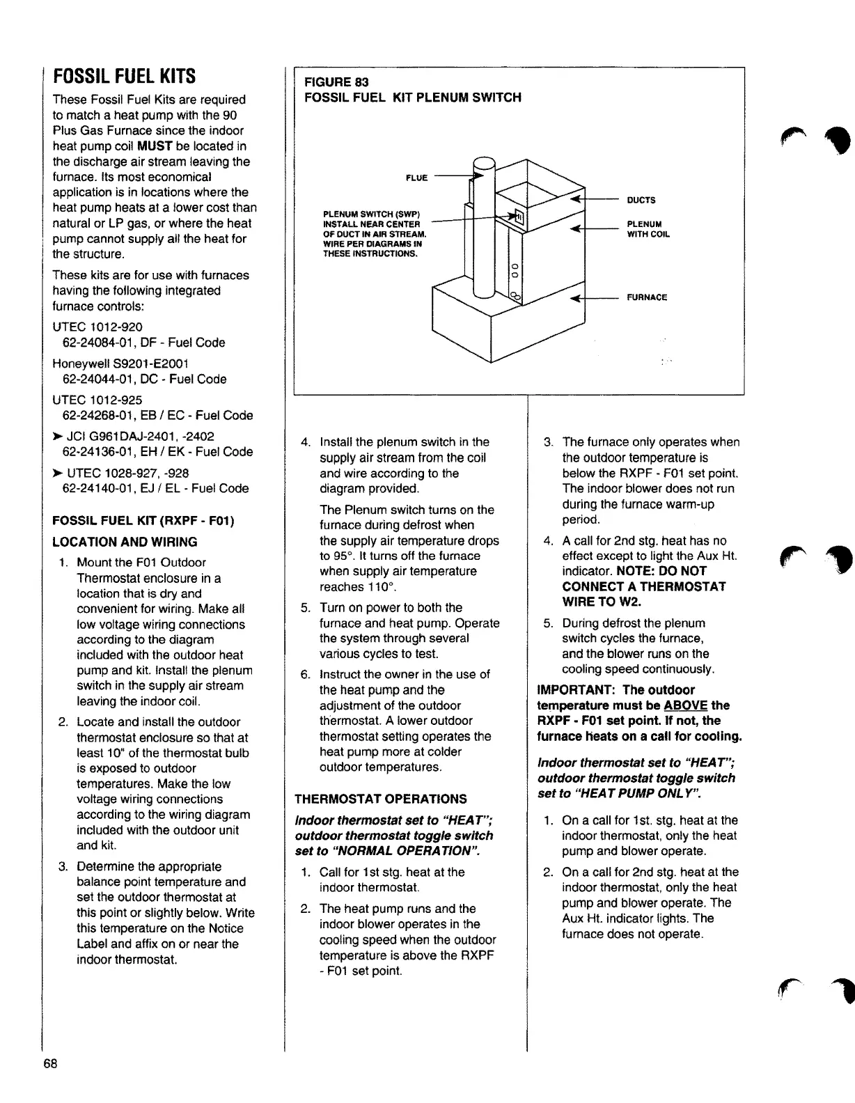
FIGURE83
FOSSIL FUEL KIT PLENUM SWITCH
PLENUM SWITCH ($WP)
INSTALL NEAR CENTER
OF DUCT IN AIR STREAM.
WIRE PER DIAGRAMS IN
THESE INSTRUCTIONS.
DUCTS
FURNACE
4. Install the plenum switch in the 3. The furnace only operates when
supply air stream from the coil the outdoor temperature is
and wire according to the below the RXPF - F01 set point.
diagram provided. The indoor blower does not run
during the furnace warm-up
The Plenum switch turns on the
period.
furnace during defrost when
the supply air temperature drops
4. A call for 2nd stg. heat has no
to 95°. It turns off the furnace effect except to light the Aux Ht.
when supply air temperature indicator.
NOTE: DO NOT
reaches 110°. CONNECT A THERMOSTAT
WIRETOW2.
5. Turn on power to both the
furnace and heat pump. Operate 5. During defrost the plenum
the system through several switch cycles the furnace,
various cycles to test. and the blower runs on the
cooling speed continuously.
6. Instruct the owner in the use of
the heat pump and the
IMPORT ANT: The outdoor
adjustment of the outdoor temperature must be ABOVE the
thermostat. A lower outdoor RXPF - F01 set point. If not, the
thermostat setting operates the
furnace Heats on a call for cooling.
heat pump more at colder
Indoor thermostat set to "HEAT";
outdoor temperatures.
outdoor thermostat toggle switch
set to "HEAT PUMP ONLY".
THERMOSTAT OPERATIONS
Indoor thermostat set to "HEAT"; 1. On a call for 1st. stg. heat at the
outdoor thermostat toggle switch indoor thermostat, only the heat
set to "NORMAL OPERATION". pump and blower operate.
1. Call for 1st stg. heat at the 2. On a call for 2nd stg. heat at the
indoor thermostat. indoor thermostat, only the heat
pump and blower operate. The
2. The heat pump runs and the
Aux Ht. indicator lights. The
indoor blower operates in the
furnace does not operate.
cooling speed when the outdoor
temperature is above the RXPF
- F01 set point.
68