--
"
CONCENTRIC HORIZONTAL VENT
hole. (3 inch pipe must be glued
KIT • RXGY • C01
to "Y" at this point, using PVC
This termination kit is for horizontal
primer and cement which
venVintake air runs and may be
conforms to ASTM D2564.)
located where 12 in. clearance 3.
From the outside, connect the
above ground level or anticipated
4 x 3 in. coupling to the inlet
snowfall can be maintained. It is pipe, using PVC primer and
coaxial requiring only one wall
cement which conforms to
penetration and is adaptable for
ASTM D2564. Be sure that the
walls up to 16 in. thick. No revision is pipe is seated in the coupling.
required for thinner walls unless
4.
Push the coupling against the
there is an installation problem. The
wall and orient the assembly so
following parts are included:
that the inlet connection to the
1.
Vent, inlet wye and inlet pipe
wye is higher than the vent
assembly.
connection. This will prevent any
2.
4 x 3 in. coupling.
moisture from running down the
3.
3 in.
x45 degree street elbow.
inlet pipe to the furnace. Caulk
around the coupling at the
Install as follows (Figure 42):
outside wait for a weatherproof
i. Cut a 4-1/8 in. diameter hole
seal.
through the wall. If the vent
5. When properly installed, the
termination length must be
vent pipe will extend outward
reduced, go to step 7.
i Oinches from the wall.
2.
Remove the 4 x 3 in. coupling
See Figure 42.
from the assembly and from
6. NOTE: If it is necessary to
inside the structure, insert the
shorten the assembly, the inlet
assembly through the wall. Wrap
(3" dia.) and vent (2" dia.) pipes
the 3 inch pipe with insulation to
must be cut off by equal
help center it in the 4-1/8 in.
amounts. The 1
O"vent to wall
distance must be maintained.
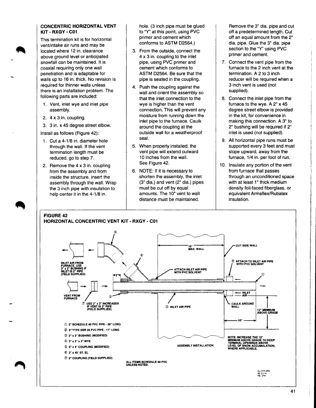
FIGURE42
HORIZONTAL CONCENTRIC VENT KIT· RXGY • C01
-
INLET AIR FROM
FURNACE.USE
3"
x2" BUSHING IF
INLET IS 2" PIPE
(FIEt.D SUPPLIED)
-
- rn-
~~~~fM
r @
@
(t USE 2" x3" INCREASER
IF VENT IS 3" PIPE
(FIELD SUPPLIED!
(D 2" SCHEDULE 40 PVC PIPE • 38" LONG
~ 3" TYPE SOIi 26 PVC PIPE • 17" LONG
@ 2" x 3" BUSHING (MODIFIED)
@ 3"x3"x3"WYE
@ 3" x 4" COUPLING (MODIFIED)
@ 3"x45'ST.EL
(l) 2" COUPLING (FIEI.D SUPPLIED)
16"
MAX.WALL
ATTACH INLET AIR PIPE
WITH PVC SOLVENT
(Zi INLET AIR PIPE
ALL ITEMS SCHEDULE 40 PVC
UNLESS NOTEO.
ASSEMBLY INSTALLATION
7.
8.
9.
10.
Remove the 3" dia. pipe and cut
off a predetermined length. Cut
off an equal amount from the 2"
dia. pipe. Glue the 3" dia. pipe
section to the "Y" using PVC
primer and cement.
Connect the vent pipe from the
furnace to the 2 inch vent at the
termination. A 2 to 3 inch
reducer will be required when a
3 inch vent is used (not
supplied).
Connect the inlet pipe from the
furnace to the wye.
A 2" x 45
degree street elbow is provided
in the kit, for convenience in
making this connection.
A 3" to
2" bushing will be required if 2"
inlet is used (not supplied).
All horizontal pipe runs must be
supported every 3 feet and must
slope upward, away from the
furnace, 1/4 in. per foot of run.
Insulate any portion of the vent
from furnace that passes
through an unconditioned space
with at least 1 " thick medium
density foil-faced fiberglass, or
equivalent Armaflex/Rubatex
insulation.
CUT SIDE WALL
@ ATTACH TO INLET
AIR PIPE
WITH PVC SOL VENT
(D
-INLET
-AIR--4----
CAULK AROUND
WAl.L
10"
NOTE: INCREASETHE 12"
MINIMUMABOVE GRADE TO KEEP
TERMINAL OPENINGS ABOVE
LEVEL OF SNOW ACCUMULATION,
WHERE APPLICABLE.
k.L.!'4
◄
.0GN
U:l·2P'H
1"i6.7JPH
41