,
NOTE: L 1 and L2 (neutral) polarity
must be observed when making field
connections to the furnace. The
ignition control may not sense flame
if L 1 and L2 are reversed.
Make all electrical connections in
accordance with the latest edition of
the National Electrical Code
ANSI/NFPA-70 or in Canada, the
Canadian Electrical Code Part
1-CSA Standard C22.1 and local
codes having jurisdiction.
THERMOSTAT
Install the room thermostat according
to the manufacturer's instructions.
Run the thermostat leads into the
blower compartment. Connect them
as shown on the wiring diagrams.
NOTE: Thermostat wire must be #18
AWG or larger. (See Table 22).
IMPORTANT: ALWAYS DIS-
CONNECT
MAIN 115 VOLT
POWER WHEN CONNECTING
THERMOSTAT WIRES. THE
COMMON SIDE OF THE 24-VOL T
TRANSFORMER IS GROUNDED
TO THE FURNACE CABINET. IF A
LOW VOLTAGE WIRE SHORTS TO
THE CABINET OR OTHER
GROUNDED COMPONENT,
DAMAGE TO THE CONTROL
TRANSFORMER OR SOLID STATE
CONTROL
BOARD MAY RESULT.
Never install a thermostat:
1. on an outside wall,
2. where it may be influenced
by drafts,
3. near concealed hot or cold water
pipes or ducts,
4. near lighting fixtures,
5. in line of radiation from a
fireplace, or in sunlight,
6. near televisions, and radios,
7. in air streams from registers.
Locate the thermostat approximately
five feet up from the floor.
NOTE: Always connect the
thermostat "Y" wire to the "Y"
terminal on the control board. Also
connect the wire to the condensing
unit contactor at the "Y" terminal on
the control board.
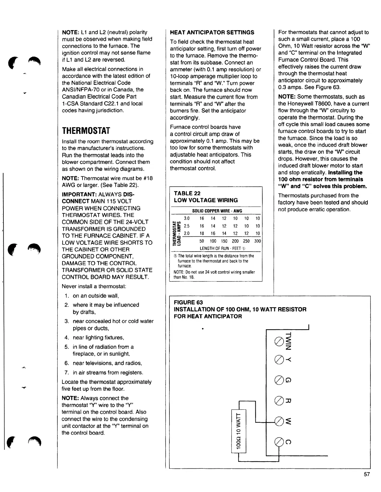
For thermostats that cannot adjust to
such a small current, place a 100
HEAT ANTICIPATOR SETTINGS
To field check the thermostat heat
Ohm, 10 Watt resistor across the
uW"
anticipator setting, first turn off power
and "C" terminal on the Integrated
to the furnace. Remove the thermo-
Furnace Control Board. This
stat from its subbase. Connect an
effectively raises the current draw
ammeter (with 0.1 amp resolution) or
through the thermostat heat
10-loop amperage multiplier loop to
anticipator circuit to approximately
terminals "R" and "W." Turn power
0.3 amps. See Figure 63.
back on. The furnace should now
start. Measure the current flow from
NOTE: Some thermostats, such as
terminals "R" and "W" after the
the Honeywell T8600, have a current
burners fire. Set the anticipator
flow through the "W" circuitry to
accordingly.
operate the thermostat. During the
off cycle this small load causes some
Furnace control boards have
furnace control boards to try to start
a control circuit amp draw of
the furnace. Since the load is so
approximately 0.1 amp. This may be
weak, once the induced draft blower
too low for some thermostats with
starts, the draw on the
"W' circuit
adjustable heat anticipators. This
drops. However, this causes the
condition should not affect
induced draft blower motor to start
thermostat control.
and stop erratically.
Installing the
100 ohm resistor from terminals
"W" and "C" solves this problem.
TABLE22
Thermostats purchased from the
LOW VOLTAGE WIRING
factory have been tested and should
not produce erratic operation.
SOLIDCOPPERWIRE• AWG
3.0 16 14 12 10 10
10
gi
2.5 16 14 12 12 10 10
~~
2 , 2.0 18 16 14 12 12 10
«~-----------
!:l!o 50 100 150 200 250 300
........
LENGTHOF RUN • FEET ·1)
© The total wire length is the distance from the
furnaceto the thermostat and back to the
furnace.
NOTE:Do not use 24 volt control wiring smaller
than No. 18.
FIGURE 63
INSTALLATION OF 100 OHM, 10 WATT RESISTOR
FOR HEAT ANTICIPATOR
0~
--i
z
0-<
0
57