2. DOWNFLOW UNITS
To convert to left side drainage, first
remove the drainage hoses from the
trap. Remove the trap from its
mounting bracket, rotate it 180°, and
mount in place with the drainage
elbow pointing to the left. Reattach
the drain hoses. Remove the plastic
drainage knockout from the left side.
A length of 1/2" PVC pipe is provided
for left hand drainage. Glue one end
of the pipe to the elbow in the trap.
Cut the pipe so that it extends
through the left cabinet side one
inch. Connect the 1/2" tee to the pipe
with a 5" riser and drain tube as
listed above.
IMPORTANT: WHEN CHANGING
TO THE LEFT SIDE, INTER-
CHANGE THE RUBBER BUSHING
ON THE RIGHT SIDE WITH THE
HOLE PLUG ON THE LEFT SIDE.
THE HOLE PLUG MUST BE IN
PLACE TO ASSURE THAT THE
COMPARTMENT IS SEALED.
CONDENSATE DRAIN
INSTALLATION FOR
HORIZONTAL APPLICATIONS
Refer to Figure 54 for steps 1
through 5.
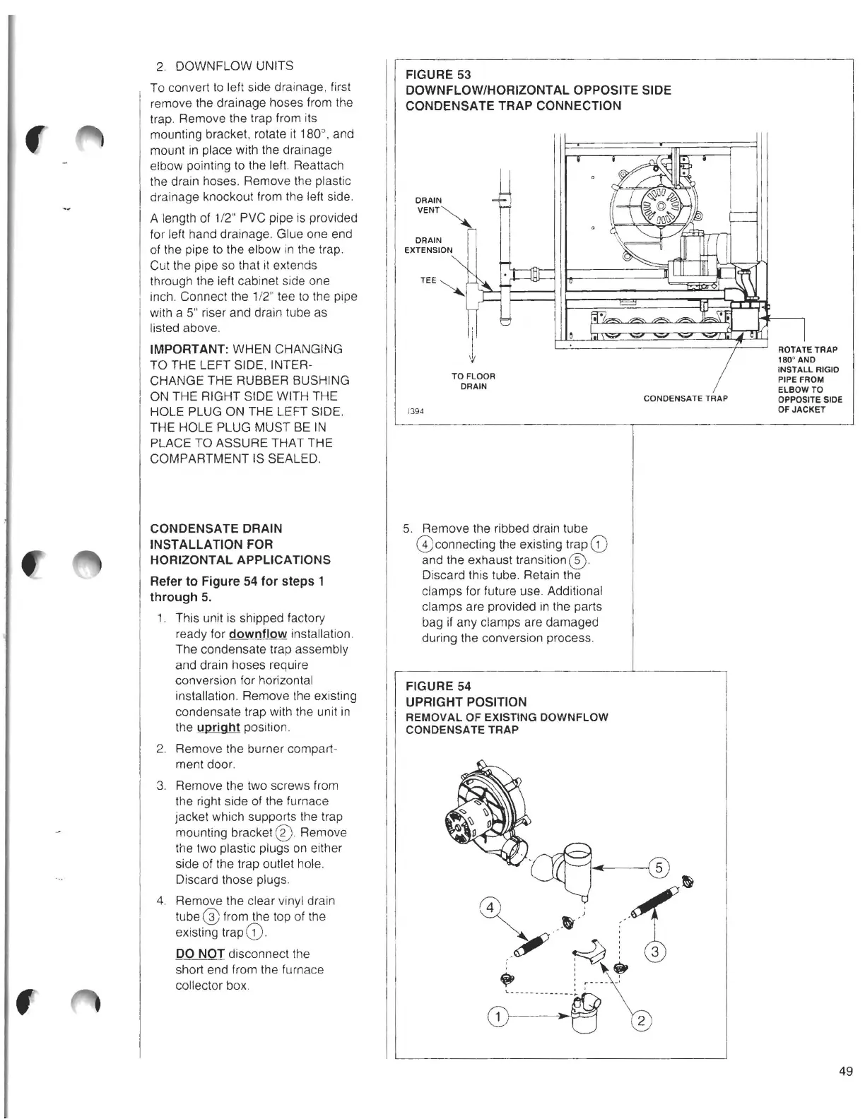
1. This unit is shipped factory
ready for downflow installation.
The condensate trap assembly
and drain hoses require
conversion for horizontal
installation. Remove the existing
condensate trap with the unit in
the upright position.
2. Remove the burner compart-
ment door.
3. Remove the two screws from
the right side of the furnace
jacket which supports the trap
mounting bracket® Remove
the two plastic plugs on either
side of the trap outlet hole.
Discard those plugs.
4. Remove the clear vinyl drain
tube@ from the top of the
existing trap
G).
DO NOT disconnect the
short end from the furnace
collector box.
f
FIGURE 53
DOWNFLOW/HORIZONTAL OPPOSITE SIDE
CONDENSATE TRAP CONNECTION
DRAIN
VENT~
DRAIN
EXTENSION
ROTATE TRAP
180' AND
INSTALL RIGID
PIPE FROM
ELBOW
TO
CONDENSATE TRAP
OPPOSITE SIDE
1394
OF JACKET
TD FLOOR
DRAIN
5. Remove the ribbed drain tube
G)connecting the existing trap
(D
and the exhaust transition@).
Discard this tube. Retain the
clamps for future use. Additional
clamps are provided in the parts
bag if any clamps are damaged
during the conversion process.
FIGURE 54
UPRIGHT POSITION
REMOVAL OF EXISTING DOWNFLOW
CONDENSATE TRAP
49