b. The 24 VAC supply to both
control boards must be in
phase with each other.
c. Connect the "C," "W" and
'TWIN'' terminals to
counterparts on each control.
d. Both control boards must
have switch # 1 in the "ON"
position.
e. Control board "ONE" must
have switch #2 in the "ON"
position. Control board
"TWO" must have switch #2
in the "OFF" position for
single stage heat.
2. Two Stage Operation
a. Follow above instructions
except connect "W2" on the
thermostat to "W" on control
board "TWO."
b. Control board "TWO" must
be the slave (not connected
to the thermostat) in two-
stage operation.
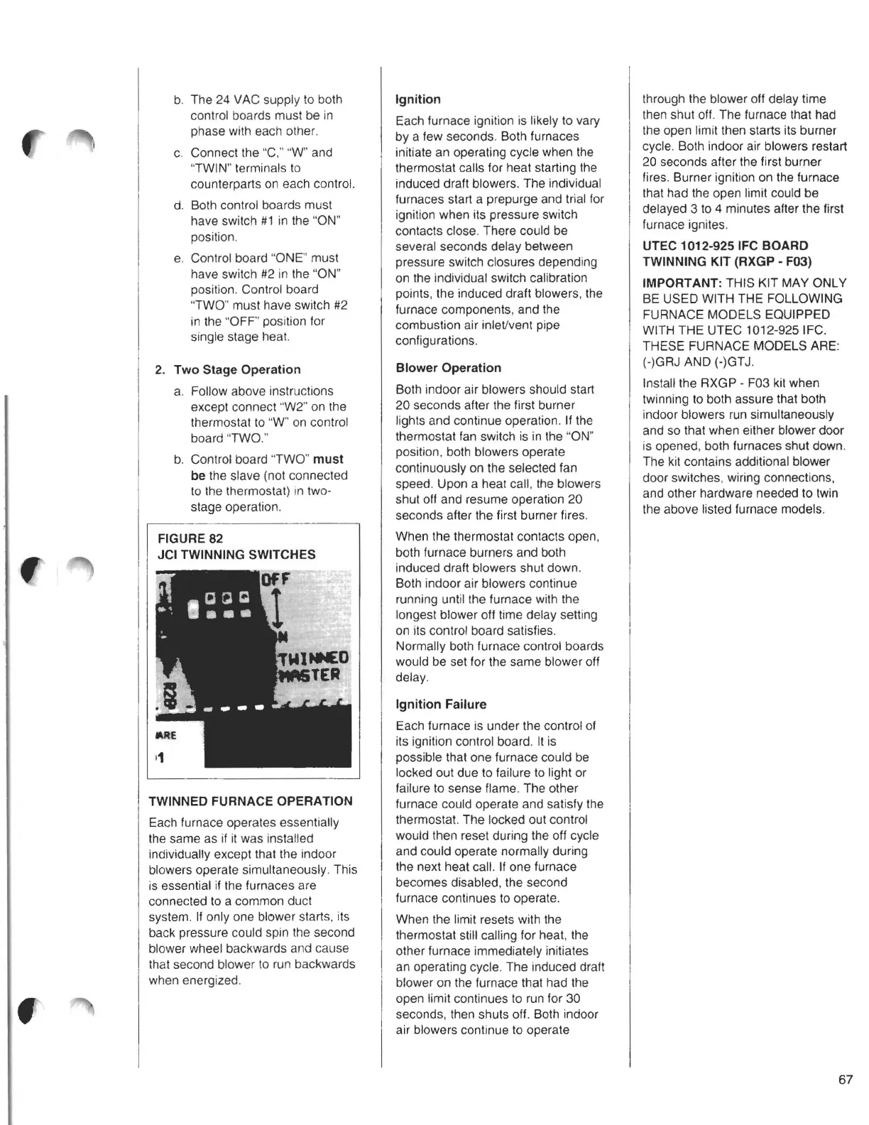
FIGURE 82
JCI TWINNING SWITCHES
TWINNED FURNACE OPERATION
Each furnace operates essentially
the same as if it was installed
individually except that the indoor
blowers operate simultaneously. This
is essential if the furnaces are
connected to a common duct
system. If only one blower starts, its
back pressure could spin the second
blower wheel backwards and cause
that second blower to run backwards
when energized.
Ignition
Each furnace ignition is likely to vary
by a few seconds. Both furnaces
initiate an operating cycle when the
thermostat calls for heat starting the
induced draft blowers. The individual
furnaces start a prepurge and trial for
ignition when its pressure switch
contacts close. There could be
several seconds delay between
pressure switch closures depending
on the individual switch calibration
points, the induced draft blowers, the
furnace components, and the
combustion air inlet/vent pipe
configurations.
Blower Operation
Both indoor air blowers should start
20 seconds after the first burner
lights and continue operation. If the
thermostat fan switch is in the "ON"
position, both blowers operate
continuously on the selected fan
speed. Upon a heat call, the blowers
shut off and resume operation 20
seconds after the first burner fires.
When the thermostat contacts open,
both furnace burners and both
induced draft blowers shut down.
Both indoor air blowers continue
running until the furnace with the
longest blower off time delay setting
on its control board satisfies.
Normally both furnace control boards
would be set for the same blower off
delay.
Ignition Failure
Each furnace is under the control of
its ignition control board. It is
possible that one furnace could be
locked out due to failure to light or
failure to sense flame. The other
furnace could operate and satisfy the
thermostat. The locked out control
would then reset during the off cycle
and could operate normally during
the next heat call. If one furnace
becomes disabled, the second
furnace continues to operate.
When the limit resets with the
thermostat still calling for heat, the
other furnace immediately initiates
an operating cycle. The induced draft
blower on the furnace that had the
open limit continues to run for 30
seconds, then shuts off. Both indoor
air blowers continue to operate
through the blower off delay time
then shut off. The furnace that had
the open limit then starts its burner
cycle. Both indoor air blowers restart
20 seconds after the first burner
fires. Burner ignition on the furnace
that had the open limit could be
delayed 3 to 4 minutes after the first
furnace ignites.
UTEC 1012-925 IFC BOARD
TWINNING KIT (RXGP - F03)
IMPORTANT: THIS KIT MAY ONLY
BE USED WITH THE FOLLOWING
FURNACE MODELS EQUIPPED
WITH THE UTEC 1012-925 IFC.
THESE FURNACE MODELS ARE:
(-)GRJ AND (-)GTJ.
Install the RXGP - F03 kit when
twinning to both assure that both
indoor blowers run simultaneously
and so that when either blower door
is opened, both furnaces shut down.
The kit contains additional blower
door switches, wiring connections,
and other hardware needed to twin
the above listed furnace models.
67