VENTING
EXHAUST PIPE TERMINATIONS
Standard vertical terminations
Vertical through-the-roof applications
r
do not require an exhaust terminal.
1. The exhaust vent must
terminate at least 12 inches
above the intake air termination.
The exhaust vent termination
for 90,000 - 120,000 BTUH
input models is 2 inch
PVC pipe.
2. Reduce the exhaust vent
termination for 45,000 - 75,000
BTUH input furnaces from
2 inches to 1-1/2 inches at the
air intake level. Extend this
1-1/2 Inch pipe 12 inches
beyond the air intake.
See Figure 40.
Standard horizontal terminations
For direct vent systems, the standard
termination is 2" PVC pipe extending
12• from the wall for furnaces with
inputs of 90,000 -120,000 BTU.
1. Install a 2" coupling at the
outside wall to prevent the
termination from being pushed
inward.
2. When 3" pipe is used between
the furnace and outside wall,
reduce the 3" pipe to 2" before
penetrating the wall. Extend the
2" pipe 12" past the outside wall.
For 45,000 - 75,000 BTUH input
furnaces, the standard termination is
1-1/2" PVC pipe extending outward
12" from the wall.
1. Install a 2" to 1-1 /2" coupling at
the outside wall to prevent
pushing the termination back
into the wall. See Figure 41,
Detail
8.
2. Install a length of 1 • 1 /2" pipe so
that it extends 12" beyond the
outside wall.
The exhaust termination must be at
least 12" above grade and must be
positioned with respect to the air
intake as shown in Figure 41,
Detail C. Refer to the section on
alternate venting options when
higher snow levels are anticipated.
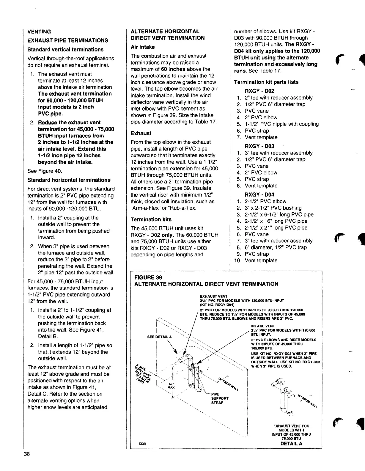
ALTERNATE HORIZONTAL
DIRECT VENT TERMINATION
Air intake
The combustion air and exhaust
terminations may be raised a
maximum of
60 Inches above the
wall penetrations to maintain the 12
inch clearance above grade or snow
level. The top elbow becomes the air
intake termination. Install the wind
deflector vane vertically in the air
inlet elbow with PVC cement as
shown in Figure 39. Size the intake
pipe diameter according to Table 17.
Exhaust
From the top elbow in the exhaust
pipe, install a length of PVC pipe
outward so that it terminates exactly
12 inches from the wall. Use a 1 1/2"
termination pipe extension for 45,000
BTUH through 75,000 BTUH units.
AUothers use a 2" termination pipe
extension. See Figure 39. Insulate
the vertical riser with minimum 1 /2"
thick, closed cell insulation, such as
"Arm-a-Flex" or "Rub-a-Tex."
Termination kits
The 45,000 BTUH unit uses kit
RXGY - 002
only. The 60,000 BTUH
and 75,000 BTUH units use either
kits RXGY - 002 or RXGY - 003
depending on pipe lengths and
FIGURE 39
number of elbows. Use kit RXGY -
003 with 90,000 BTUH through
120,000 BTUH units.
The RXGY •
D04 kit only applies to the 120,000
BTUH unit using the alternate
termination and excessively long
runs.
See Table 17.
Termination kit parts lists
RXGY- D02
1. 2" tee with reducer assembly
2. 1/2" PVC 6" diameter trap
3. PVC vane
4. 2" PVC elbow
5. 1-1/2" PVC nipple with coupling
6. PVC strap
7. Vent template
RXGY- D03
1. 3" tee with reducer assembly
2. 1/2" PVC 6" diameter trap
3. PVC vane
4. 2" PVC elbow
5. PVC strap
6. Vent template
RXGY-D04
1. 2-1/2" PVC elbow
2. 3" x 2-1/2" PVC bushing
3. 2-1/2" x 6-1/2" long PVC pipe
4. 2-1/2" x 16'' long PVC pipe
5. 2-1 /2" x 21" long PVC pipe
6. PVC vane
7. 3" tee with reducer assembly
8. 6" diameter, 1/2" PVC trap
9. PVC strap
10. Vent template
ALTERNATE HORIZONTAL DIRECT VENT TERMINATION
60"
MAX.
i
j, /
1339
EXHAUST VENT
2¼" PVC FOR MODELS WITH 120,000 BTU INPUT
(KIT NO. RXGY•D04)
2• PVC FOR MODELS WITH INPUTS OF 90,000 THAU 120,000
BTU. REDUCE TO 1½" FOR MODELS WITH INPUTS OF 45,000
THRU 75,000 BTU, ELBOWS AND RISERS ARE 2" PVC.
PIPE
SUPPORT
STRAP
INTAKE VENT
2½" PVC FOR MODELS WITH 120,000
BTIJINPUT.
2" PVC ELBOWS AND RISER MODELS
WITH INPUTS OF 45,000 THRU
105,000 BTU.
USE KIT NO. RXGY-002 WHEN
2" PIPE
IS USED BETWEEN FURNACE AND
OUTSIDE WALL. USE KIT NO. RXGY-003
WHEN
3" PIPE IS USED.
EXHAUST VENT FOR
MODELS WITH
INPUT OF 45,000 THRU
75,000BTU
DETAILA
4
38