~
f
6.
Caulk all cracks, seams and
joints within 6 feet horizontally
and above and below the vent.
7.
Do not terminate behind any
area that may allow the flue
gases to stagnate or recirculate.
8. Painted surfaces must be sound
and in good condition with
no cracking, peeling, etc.
Painted surfaces will require
maintenance.
9
Do not expose 3" x 2" PVC
reducer/bushing to outdoor
ambient temperatures.
10.
Do not terminate where the
flue gases can stagnate or
recirculate.
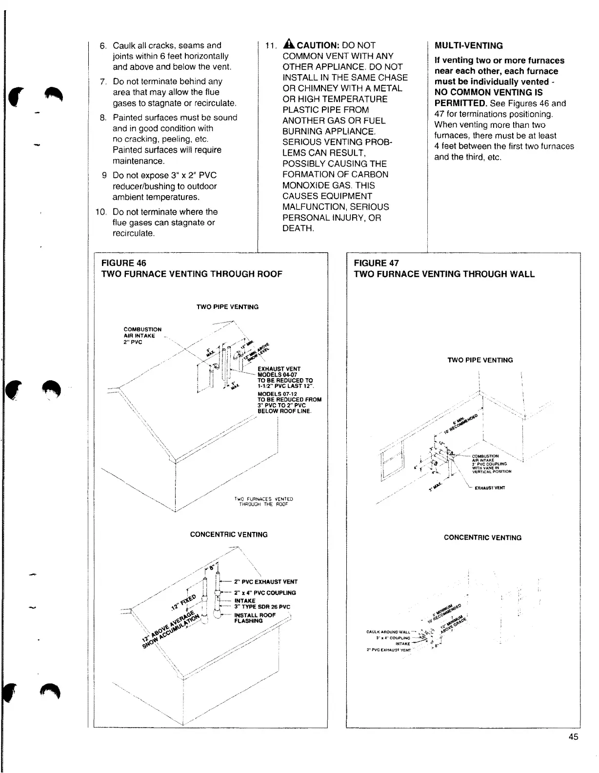
FIGURE 46
TWO FURNACE VENTING THROUGH ROOF
COMBUSTION
AIR INTAKE
2"PVC
TWO PIPE VENTING
Two FURNACES VENTED
THROUGH THE ROOF
CONCENTRIC VENTING
11. A CAUTION: DO NOT MUL Tl-VENTING
COMMON VENT WITH ANY
If venting two or more furnaces
OTHER APPLIANCE DO NOT
near each other, each furnace
INSTALL IN THE SAME CHASE
must be individually vented -
OR CHIMNEY WITH A METAL
NO COMMON VENTING IS
OR HIGH TEMPERATURE
PERMITTED. See Figures 46 and
PLASTIC PIPE FROM
47 for terminations positioning.
ANOTHER GAS OR FUEL
When venting more than two
BURNING APPLIANCE.
furnaces, there must be at least
SERIOUS VENTING PROB·
4 feet between the first two furnaces
LEMS CAN RESULT,
and the third, etc.
POSSIBLY CAUSING THE
FORMATION OF CARBON
MONOXIDE GAS. THIS
CAUSES EQUIPMENT
MALFUNCTION, SERIOUS
PERSONAL INJURY, OR
DEATH.
FIGURE47
TWO FURNACE VENTING THROUGH WALL
TWO PIPE VENTING
CONCENTRIC VENTING
- ,o
c•uc,•.:~~=:~,r J
ltITAKE •
~
8'
2"' PvC EXHAUST VENT
45