CONNECTING THE VENT
TO THE FURNACE
IMPORT ANT: Clean and debur all
pipe cuts. The shavings must not
block the exhaust. inlet or
condensate drain pipes.
1. UPFLOW FURNACE
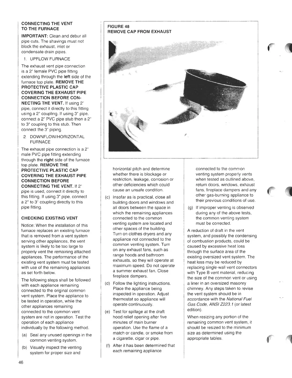
The exhaust vent pipe connection
is a 2" female PVC pipe fitting
extending through the left side of the
furnace top plate. REMOVE THE
PROTECTIVE PLASTIC CAP
COVERING THE EXHAUST PIPE
CONNECTION BEFORE CON-
NECTING THE VENT. If using 2"
pipe, connect it directly to this fitting
using a 2" coupling. If using 3" pipe.
connect a 2" PVC pipe stub then a 2"
to 3" coupling to this stub. Then
connect the 3" piping.
2. DOWNFLOW/HORIZONTAL
FURNACE
The exhaust pipe connection is a 2"
male PVC pipe fitting extending
through the right side of the furnace
top plate. REMOVE THE
PROTECTIVE PLASTIC CAP
COVERING THE EXHAUST PIPE
CONNECTION BEFORE
CONNECTING THE VENT. If 2"
pipe is used, connect it directly to
this fitting. If using 3" pipe, connect
a 2" to 3" coupling directly to this
pipe fitting.
CHECKING EXISTING VENT
Notice: When the installation of this
furnace replaces an existing furnace
that is removed from a vent system
serving other appliances, the vent
system is likely to be too large to
properly vent the remaining attached
appliances. The performance of the
existing vent system must be tested
with use of the remaining appliances
as set forth below.
The following steps shall be followed
with each appliance remaining
connected to the original common
vent system. Place the appliance to
be tested in operation, while the
other appliances remaining
connected to the common vent
system are not in operation. Test the
operation of each appliance
individually by the following method.
(a) Seal any unused openings in the
common venting system.
(b) Visually inspect the venting
system for proper size and
FIGURE 48
REMOVE CAP FROM EXHAUST
horizontal pitch and determine
whether there is blockage or
restriction, leakage, corrosion
or
other deficiencies which could
cause an unsafe condition.
(c) Insofar as is practical, close all
building doors and windows and
all doors between the space in
which the remaining appliances
connected to the common
venting system are located and
other spaces of the building.
Turn on clothes dryers and any
appliance not connected to the
common venting system. Turn
on any exhaust fans, such as
range hoods and bathroom
exhausts, so they will operate at
maximum speed. Do not operate
a summer exhaust fan. Close
fireplace dampers.
(d) Follow the lighting instructions.
Place the appliance being
inspected in operation. Adjust
thermostat so appliance will
operate continuously.
(e) Test for spillage at the draft
hood relief opening after five
minutes of main burner
operation. Use the flame of a
match or candle, or smoke from
a cigarette, cigar or pipe.
(f) After it has been determined that
each remaining appliance
connected to the common
venting system properly vents
when tested as outlined above,
return doors, windows, exhaust
fans, fireplace dampers and any
other gas-burning appliance to
their previous conditions of use.
(g) If improper venting is observed
during any of the above tests,
the common venting system
must be corrected.
A reduction of draft in the vent
system, and possibly the condensing
of combustion products, could be
caused by excessive heat loss
through the surface area of the
existing oversized vent system. The
heat loss may be reduced by
replacing single-wall vent connectors
with Type B vent material, reducing
the size of the common vent or using
a liner in an oversized masonry
chimney. Any steps taken to revise
the vent system should be in
accordance with the
National Fuel
Gas Code,
ANSI Z223.1 (or latest
edition).
When resizing any portion of the
remaining common vent system, it
should be resized to the minimum
size as determined using the
appropriate tables.
46