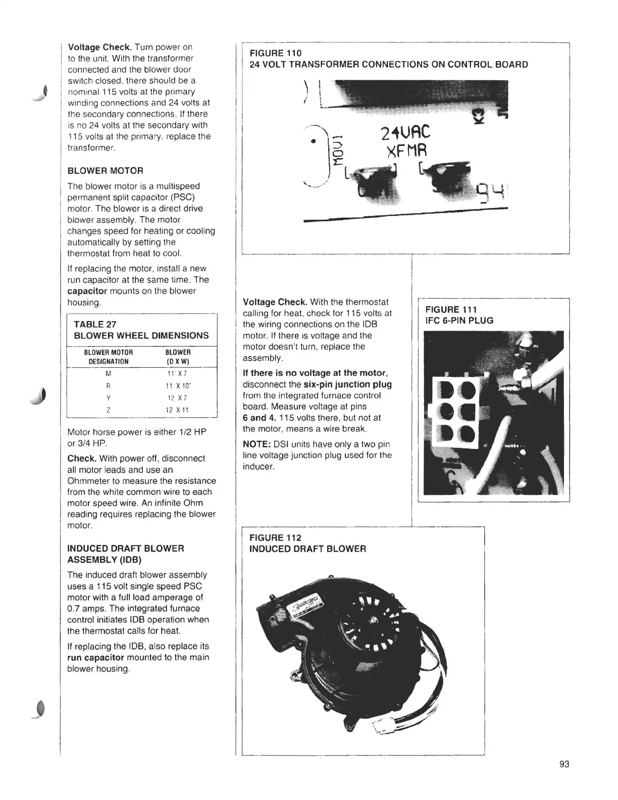
Voltage Check. Turn power on
to the unit. With the transformer
connected and the blower door
switch closed. there should be a
nominal 115 volts at the primary
winding connections and 24 volts at
the secondary connections. If there
is no 24 volts at the secondary with
115 volts at the primary. replace the
transformer.
BLOWER MOTOR
The blower motor is a multispeed
permanent split capacitor (PSC)
motor. The blower is a direct drive
blower assembly. The motor
changes speed for heating or cooling
automatically by setting the
thermostat from heat to cool.
If replacing the motor, install a new
run capacitor at the same time. The
capacitor mounts on the blower
housing.
TABLE 27
BLOWER WHEEL DIMENSIONS
BLOWERMOTOR
BLOWER
DESIGNATION
(OXW)
M
11 X 7
R
11 X 10·
y
12 X 7
z
12 X 11
Motor horse power is either 1/2 HP
or 3/4 HP.
Check. With power off, disconnect
all motor leads and use an
Ohmmeter to measure the resistance
from the white common wire to each
motor speed wire. An infinite Ohm
reading requires replacing the blower
motor.
INDUCED DRAFT BLOWER
ASSEMBLY (IDB)
The induced draft blower assembly
uses a 115 volt single speed PSC
motor with a full load amperage of
0.7 amps. The integrated furnace
control initiates IDB operation when
the thermostat calls for heat.
If replacing the IDB, also replace its
run capacitor mounted to the main
blower housing.
J
FIGURE 110
24 VOLT TRANSFORMER CONNECTIONS ON CONTROL BOARD
2iUAC
XFMR
Voltage Check. With the thermostat
calling for heat, check for 115 volts at
the wiring connections on the IDB
motor. If there is voltage and the
FIGURE 112
INDUCED DRAFT BLOWER
L
FIGURE 111
IFC 6-PIN PLUG
motor doesn't turn, replace the
assembly.
If there is no voltage at the motor,
disconnect the six-pin junction plug
from the integrated furnace control
board. Measure voltage at pins
6 and 4. 115 volts there, but not at
the
motor, means a wire break.
NOTE: OSI units have only a two pin
line voltage junction plug used for the
inducer.
93