Commander SE Advanced User Guide 135
Issue Number: 4
Sizing an appropriate thermal overload relay
Calculate the maximum permissible continuous current through the braking resistor as follows:
Where:
P
R
is the power rating of the resistor to be used.
R is the actual value of the braking resistor (not the calculated).
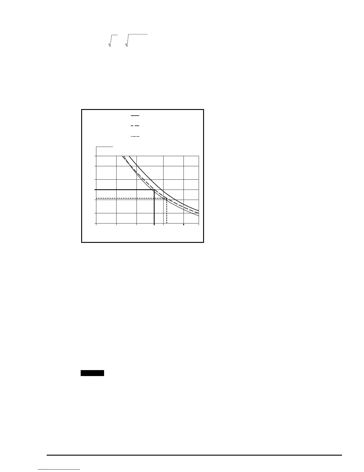
Use the tripping curves for the chosen manufacturer of thermal overload relay in order to find the overload factor (F) that will
cause the relay to trip after 10 seconds.
Figure 5-4 Example tripping curves for the Telemecanique thermaloverload relays type LR-Dx3xx
Calculate the current setting required for the thermal overload relay as follows:
Select a model of thermal overload relay that can be set at 1.1A (e.g. Telemecanique LR2-D1306).
Calculate the maximum current that could flow through the resistor (e.g. due to the braking transistor becoming short circuit)
as follows:
Calculate the overload factor for this condition as follows:
Use the tripping curves to find the time that the thermal overload relay will take to trip (e.g. 5 seconds approximately).
Check that the braking resistor can tolerate the overload current for this duration.
Braking resistors must be installed equipped with a thermal overload device.
Resistors intended for braking duty should be capable of tolerating thermal shock. ‘Pulse rated’ resistors are
recommended.
The resistance value calculated above does not take into account any tolerance in the resistance value.
The power ratings above are at the limit of satisfactory operation and thus a 10% safety factor should be built in to
ensure any tolerances do not add up to cause overvoltage trips. This could be critical where inaccurate values are
used for inertia etc. This safety factor should be increased where necessary to incorporate any sort of inaccuracy in
values used.
I
R
max
P
R
R
-------
2.3 10
3
×
120
------------------------ 4.4A== =
0.5 1 2 5 10 17
1
2
5
10
20
50
100
Balanced operation 3-phase,
from cold state
Time (s)
x current setting (F)
Balanced operation 2-phase,
from cold state
Balanced operation, 3-phase,
after a long period of set
current flow (hot state)
4
I
SET
I
SET
F
-----------
4.4
4
--------
1.1A===
I
Rpk
V
R
R
-------
780
120
----------
6.5A== =
F
SC⁄
I
Rpk
I
SET
-----------
6.5
1.1
--------
5.9===
NOTE