134 Commander SE Advanced User Guide
Issue Number: 4
Now using the required deceleration time of 10 seconds, calculate the required braking torque:
Now calculate the braking power:
Since braking occurs intermittently, the resistor can be rated for intermittent rather than continuous power dissipation so that
the overload factor of the resistor can be used. This factor can be obtained from the cooling curves for resistor type that is
being used. See the following example:
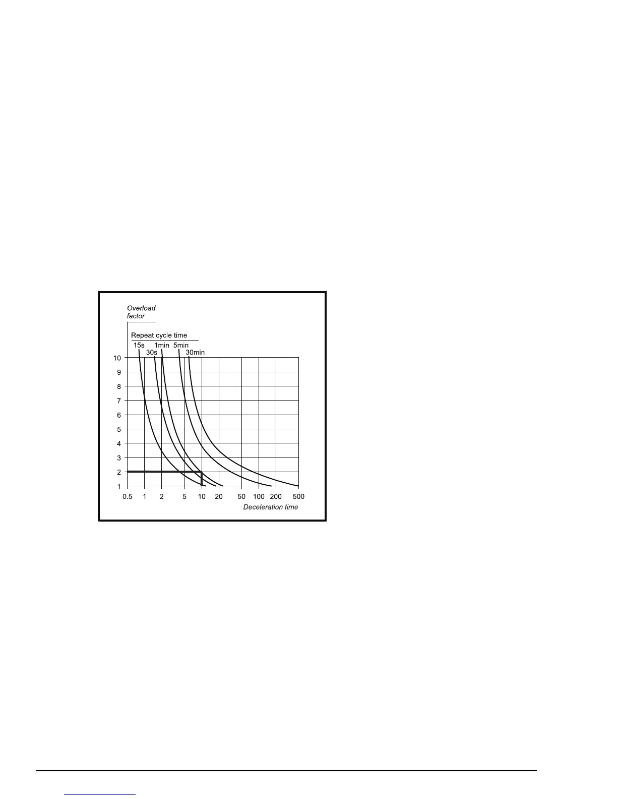
Figure 5-3 Examples cooling curves for power resistors (in practice, refer to the cooling curves for the resistor to
be used)
The cooling curve indicates that for a braking time of 10 seconds and a repeat cycle time of 60 seconds, the overall factor (F)
is 2.0.
Calculate the required power rating of the resistor:
Now calculate the value of the braking resistor:
For this example use 120Ω which is the nearest value in the E12 range of resistors.
In practice, use a resistor having a preferred value close to and lower than the calculated value. This is because the
calculated value would cause the braking transistor to be switched on almost continuously during braking. In this case, the
drive will not have full control of the DC Bus voltage. A lower value of braking resistor will cause the braking transistor to act
as a chopper which will then allow the drive to control the DC Bus voltage more accurately.
This reduction in value does not increase the power dissipation since the average voltage across the resistor is reduced by
the braking transistor operating as a chopper.
M
b
2 π× 1450×
30 10×
--------------------------------
=
M
b
30.4Nm=
P
b
M
b
π× n×
30 10
3
×
---------------------------
=
30.4 π× 1450×
30 10
3
×
----------------------------------------
=
4.6kW=
P
R
P
b
F
------
4.6 10
3
×
2.0
------------------------
2.3kW== =
R
max
VR()
2
P
b
----------------
780
2
4.6 10
3
×
------------------------
132Ω== =