Maintenance Manual SP 40
Rev. 005
108
Chapter 5
Test & Diagnostic
5.11 Monitor through serial interface
This mode can be very useful in walk-in maintenance of the printer in a repair center.
It has been developed to have the same (or in some cases much more) informations that appear on the display of
the operator panel assy directly to the serial interface connector.
It is necessary connect the printer in serial mode using the TERMINAL accessory of WIN 3.x, or HYPER-
TERMINAL accessory of WIN95 environments.
Through the serial connection all the T&D messages and informations are displayed in the video of a normal PC.
The handshaking setting must have the following parameters: XON-XOFF, 9600 baud, 8 bit, no parity, 1 stop
bit.
Setting the application for these values.
The serial connection cable has these wires :
Signal Name
Conn. 9 Female
(Host)
Conn. 9 Female
(Printer)
Signal Name
DCD/DSR 1/6 ----------------------------------- 4 DTR
RX 2 ----------------------------------- 3 TX
TX 3 ----------------------------------- 2 RX
RTS 7 ----------------------------------- 8 CTS
GND 5 ----------------------------------- 5 GND
DTR 4 ----------------------------------- 1/6 DCD/DSR
CTS 8 ----------------------------------- 7 RTS
RI 9 Not connected 9 RI
Connect shield with metallic cover Shield Connect shield with metallic cover
Table 5.12 Serial Cable Connections for Remote T&D
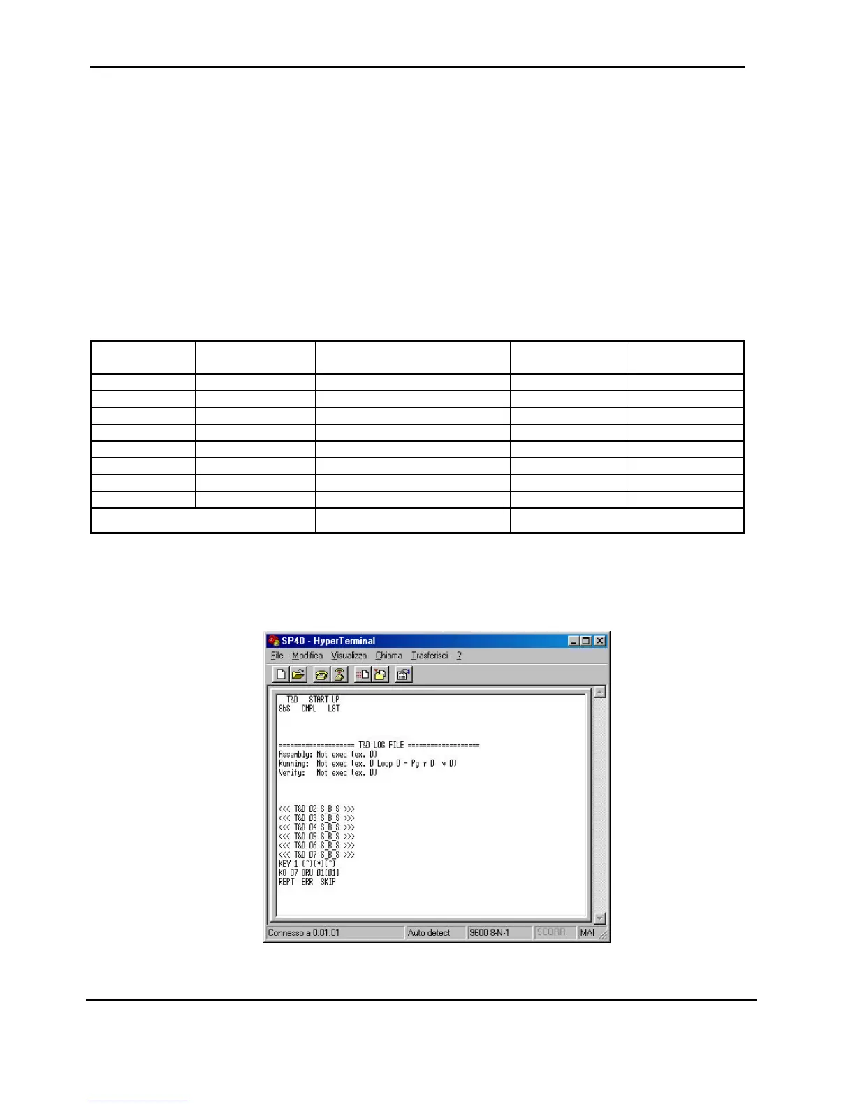
The following figure shows some steps displayed in the video.
Fig. 5.8 Remote mode display (Hyper Terminal under W98)