Maintenance Manual SP 40
Rev. 005
132
Chapter 8
Mechanical Adjustments
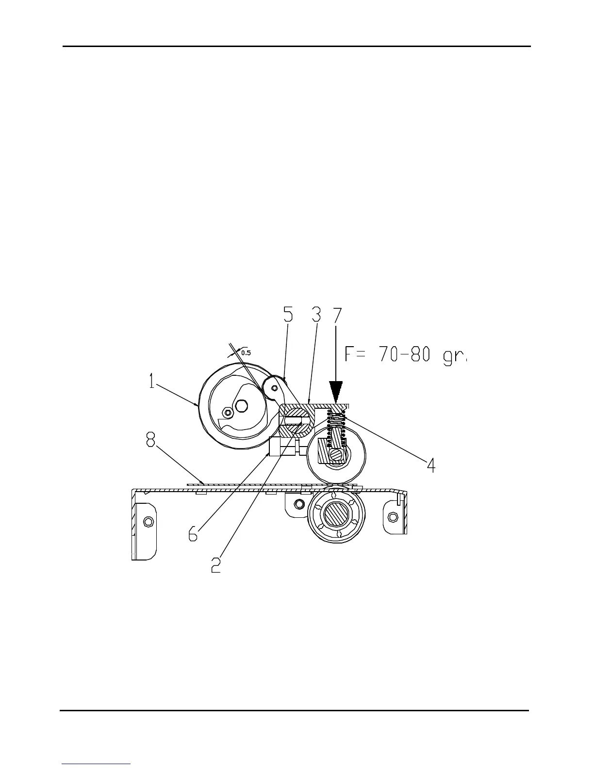
8.5 Selector Cam Adjustment
This adjustment is done to assure a correct gap between the upper and lower rollers.
The item are related to the figure 8.5. below.
Standard Value: 0.5mm ± 0.3mm
Tool: Feeler gauge
1) Turn clockwise the Cam selector (item 1) until the stop.
2) Turn the Spring bar (item 2) until the Spring pressor (item 3) are in touch with the spring (item 4).
- Put a lower force of 70-80 gr. (item 7) on the middle spring pressor.
- Put a thickness tool of 0.35mm between all the upper and lower rollers (item 8). It can be a mylar sheet
or, alternatively, 3 sheets of standard 80gr/m2 photocopy paper.
3) Move the Lever assy selector (item 5) against the Drive aligner assy putting between them a thickness of 0.3
mm and turn it against the Cam selector.
4) Tight the screw (item 6) and remove the force (item 7) and the thickness tool (item 8).
5) Turn the Spring bar (item 2)as described at point 2) and check for the gap between the wheel of the Lever
Assy (item 5) and Cam selector (item 1) must be 0.5 (± 0.3) mm.
Figure 8.5 - Selector Cam Adjustment