Maintenance Manual SP 40
Rev. 005
84
Chapter 4
Service Maintenance
4.10 Troubleshooting Tables
NOTE: For the electrical value of the electromechanical parts, please refer to chapter 7.
4.10.1 Power malfunction
SYMPTOM PROBABLE CAUSE CORRECTIVE ACTION
The printer is not powered
up
No AC power is reaching the
printer
Check power cord insertion.
Check power at wall.
Replace power cord.
The printer is not powered
up.
The switch lever don' t
correctly acting on the power
on switch of the power supply.
Check for the correct behaviour of the switch lever and
the springs on the base assy involved in the movement
of the lever. Replace the defective part.
The printer is powered on
but it is not working
properly.
An incorrect voltage is present
on power supply.
Check for the voltages present on the power supply
P01 connector. Remove the P01 from the main board.
It is recommended to apply a minimum load to the
+5VDC and +38VDC to assure the power supply
stability.
Replace the Power Supply.
Replace the Engine Board.
The printer is powered off
after short time power on.
An overload is present on
power supply.
Check for the correct cables connections.
Check for electromechanical parts impedance and
replace the faulty one.
Replace the Engine Board.
Replace Mechanical Assy
Table 4.3 Power Malfunction Troubleshooting
OUTPUT VOLTAGE:
5 VDC
+ 38 VDC
VREC from +78 to + 84 VDC @ 100 mA injected
The VREC circuit (clamping & recovery voltage) provided with an electronic circuit to clamp the collector voltage of the
needles drivers during their switching in OFF state (see chapter 7 for detail).
This circuit absorb the print head coils energy stored during the needle firing phase.
All the voltage are protected for Overvoltage, short-circuit and over-current.
The sketch of the Power supply is described at chapter 1.
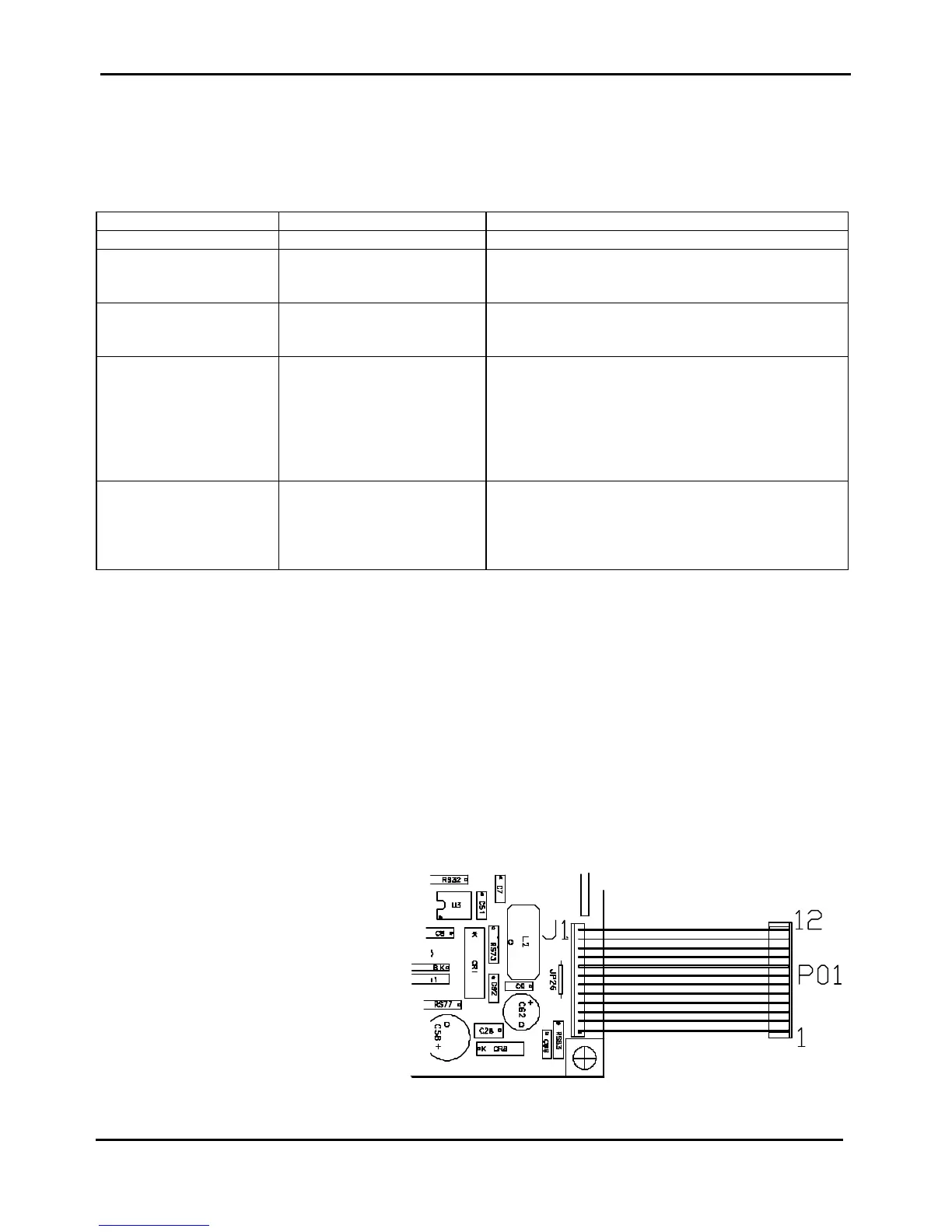
The pin out of the Power Supply is :
Figure 4.2 Power Supply pin-out
P01-01 = ZGND
P01-02 = ZGND
P01-03 = +80VClamp
P01-04 = +80VClamp
P01-05 = +5V
P01-06 = +5V
P01-07 = ZGND
P01-08 = ZGND
P01-09 = +38V
P01-10 = +38V
P01-11 = +38V
P01-12 = N.C.