Chapter 5 Test & Diagnostic
5.1 Overview
For the field maintenance of this printer, a specific Test & Diagnostic feature has been developed.
This feature is built -in the basic firmware of the printer.
The version of the T&D is reported in the T&D printout together with the version of the basic FW and (if
present) the optional LAN FW.
The T&D may be executed with the standard Operator Panel of the printer or with a specific maintenance
Operator Panel with a 16 digits LCD display to take more easy and immediate the reading of the messages.
See chapter 2.2 to remove the standard o.p. assy and install the maintenance one.
The echo of the messages is also available on the serial interface, therefore it is possible to connect the
printer with a P.C. as a remote panel to read the message.
See chapter 5.11 later in this chapter how to use it.
5.2 How to run T&D USER (with standard operator panel)
Power on with ON LINE + STATION 1 keys starts the USER T&D procedure.
ON LINE + STATION 1
Push again
STATION 1
within 3 seconds to choose the STEP BY STEP mode.
If no action is done after 3 seconds or STATION 2 is pressed, the COMPLETE T&D (VERIFY mode) will be run.
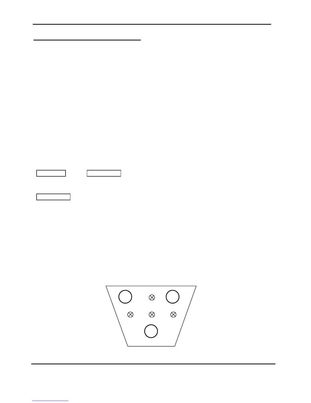
5.3 GENERAL RULES FOR T&D OPERATIONS
The display is not present on the standard Operator Panel, therefore the message are done by specifi
combinations of the leds.
l = OFF status
¡ = ON status
£ = low frequency flashing status
¥ = high frequency flashing status
Figure 5.1 Operator Panel Sketch