Maintenance Manual SP 40
Rev. 005
18
Chapter 2
Removals
2.4 Mechanical Assy
To Remove:
1) Remove the top and the main cover (see chapter 2.2).
2) Unplug the seven cables from the connector on the front side of the engine board.
From right to left, the connectors are op. panel, ribbon sensor, paper motor, home sensor, selector
motor, carriage motor.
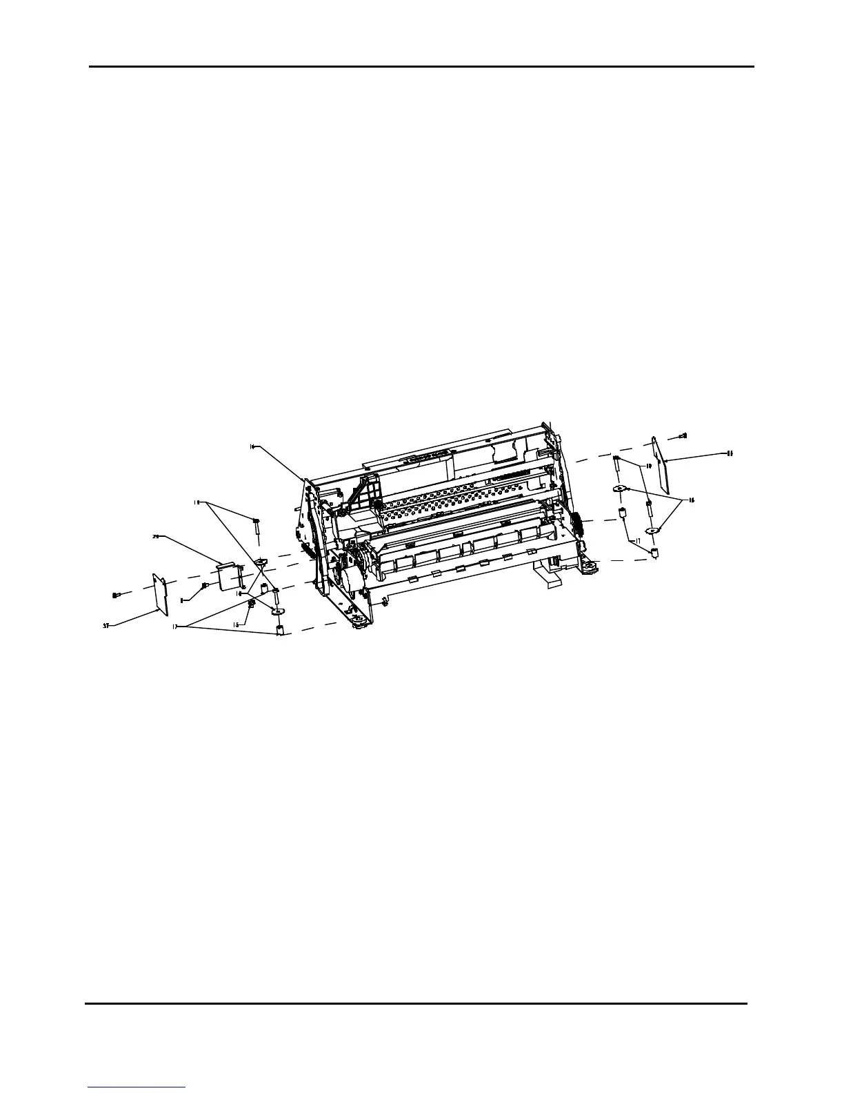
3) Unscrew the four screws (item 19 of figure 2.6) fixing the mechanical assy on the base.
4) Acting from the front side, gently rise a little bit the mechanical assembly from the base and unplug the
two print head cables from the engine board located in the rear part of the board.
5) Remove the mechanical assy from the base.
To Install:
Follow the removal step in reverse order.
Remark:
Viasual check from the right side of the printer, the correct bend of the print head cable.
They must be bended in the rear part of the printer.
Figure 2.6 - Mechanical Assy Removal