Maintenance Manual SP 40
Rev. 005
43
Chapter 2
Removals
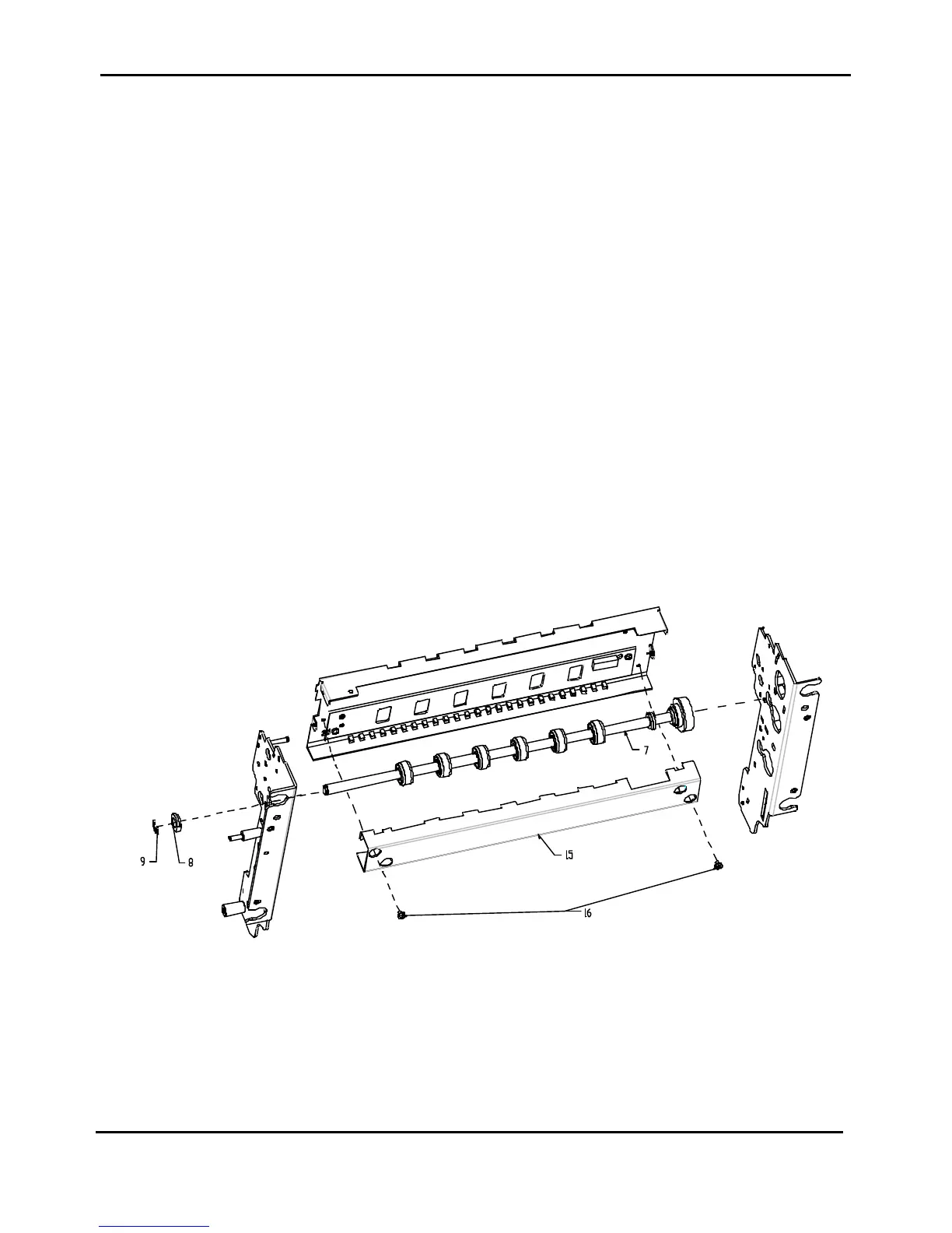
2.17 Lower Roller Assy (Front Side)
DANGER : To prevent serious personal injury from electrical shock always turn the printer off and unplug
the power cable before to remove the lower roller assy.
Lower roller assy installed under the front bed of the printer is item 7 of figure 2.20.
To Remove:
1) Remove the top and the main cover assy (see chapter 2.2).
2) Remove the inked ribbon cartridge.
3) Unplug the seven cable from the connector on the front side of the engine board.
4) Remove the four screws fixing the mechanical assy on the base.
5) Acting from the front side, gently rise the mechanical assy and unplug the print head cables from the
engine board.
6) Remove the mechanical assy.
7) Acting from the lower side of the mechanical assy, remove the two screws (item 16 of figure 2.20)
securing the bracket (item 15 of figure 2.20) to the mechanical assy and remove the bracket.
8) Unscrew the two screws securing the green wheel and remove it from the right side of the printer.
9) Drive off the paper belt from its path.
10) Remove the circlip (item 9 of figure 2.20) and the bush (item 8 of figure 2.20).
11) Acting from the lower side of the mechanical assy, extract the lower roller assy from the left frame.
12) Again from the lower side of the mechanical assy, remove the lower roller assy extracting it from the
external right side throgh the hole on right frame.
To Install:
To install, follow the removal step in reverse order.
Figure 2.20 - Lower Roller Assy (Front Side)