Ceiling Mounted Cassette Type SiEN18-622
260 System Configuration
Refer to figure 1 on page [1]
Refer to figure 1 on page [1]
• Operating procedure varies with heat pump type and
cooling only type. Contact your Daikin dealer to confirm
your system type.
• To protect the unit, turn on the main power switch 6 hours
before operation.
• If the main power supply is turned off during operation,
operation will restart automatically after the power turns
back on again.
Operate in the following order.
Operation mode selector
Press OPERATION MODE SELECTOR button several
times and select the OPERATION MODE of your choice as
follows.
COOLING OPERATION............................“ ”
HEATING OPERATION ..........................“ ”
AUTOMATIC OPERATION.....................“ ”
• In this operation mode, COOL/HEAT changeover is
automatically conducted.
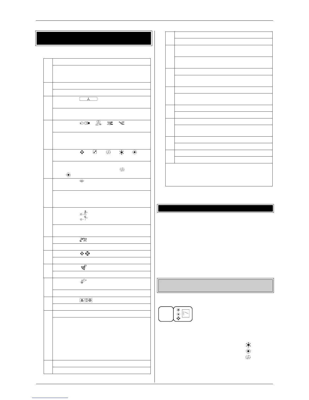
5. Name and function of each switch and display
on the remote control
This display shows the current OPERATION
MODE. For cooling only type, “” (Auto)
and “” (Heating) are not installed.
This display shows the PROGRAMMED TIME
of the system sta rt or stop.
This display shows the set temperature.
This display shows the set fan speed.
Refer to “AIR FLOW DIRECTION ADJUST”.
When the INSPECTION/TEST OPERATION
BUTTON is pre
ssed, the display shows the
system mode is in.
1
2
3
4
5
“”“”“”“”“”
6
7
8
9
10
ON/OFF BUTTON
OPERATION LAMP (RED)
The lamp lightsup during operation.
DISPLAY “”(UNDER CENTRAL-
IZED CONTROL)
When this display shows, the system is
UNDER CENTRALIZED CONTROL.
DISPLAY “ ”“”“”“”
(VENTILATION/AIR CLEANING)
This display shows that the total heat
exchange and the air cleaning unit are in
operation (These are optional accessories ).
DISPLAY
(OPERATION MODE)
DISPLAY “ TEST ” (INSPECTION/TEST
OPERATION)
DISPLAY “” (PROGRAMMED TIME)
DISPLAY “” (SET TEMPERATURE)
DISPLAY “” (FAN SPEED)
DISPLAY“” (AIR FLOW FLAP)
Press the button and the system will start.
Press the button aga in and the s ystem will
stop.
11
12
13
14
DIS PLAY “” (TIME TO CLEAN AIR
FILTER)
Refer to “HOW TO CLEAN THE AIR FILTER”.
Refer to “DEFROST OPERATION".
Refer to “PROGRAM TIMER OPERATION”.
If that particular function is not available,
pressing the button may display the words
“NOT AVAILABLE” for a few seconds.When
running multiple unitssimultaneously, the
“NOT AVAILABLE” message will only appear
if none of the indoor units is equipped with
the function. If even one unit i
s equipped with
the function, the display will not appear.
DIS PLAY “” (DEFROST)
NON-FUNCTIONING DISPLAY
TIMER MODE S TART/STOP BUTTON
6. Operation procedure
Cooling, heating, automatic, fan, and program dry
operation
15
16
17
18
19
20
21
22
Refer to “PROGRAM TIMER OPERATION”.
TIMER ON/OFF BUTTON
PROGRAMMING TIME BUTTON
TEMPERATURE SETTING BUTTON
FILTER SIGN RESET BUTTON
INSPECTION/TEST OPERATION BUT-
TON
Thisbutton isused only by qualified service
persons for maintenance purposes.
Use thisbutton for programming “STA RT
and/or STOP” time.
Use thisbutton for SETTING TEMPERA-
TURE.
Refer to “HOW TO CLEAN THE AIR FILTER”.
Press thisbutton to select OPERATION MODE.
Refer to “AIR FLOW DIRECTION ADJUST”.
Press thisbutton to select the fan speed,
HIGH or LOW, of yo
ur choice.
FAN SPEED CONTROL BUTTON
OPERATION MODE SELECTOR BUTTON
AIR FLOW DIRECTION ADJUST BUTTON
NOTE
•
For the sake of explanation, all indicationsare
shown on the display in figure 1 contrary to
actual running situations.
1