Speed measurement configuration
Proximity sensor number of pulses
Proximity sensor duty cycle
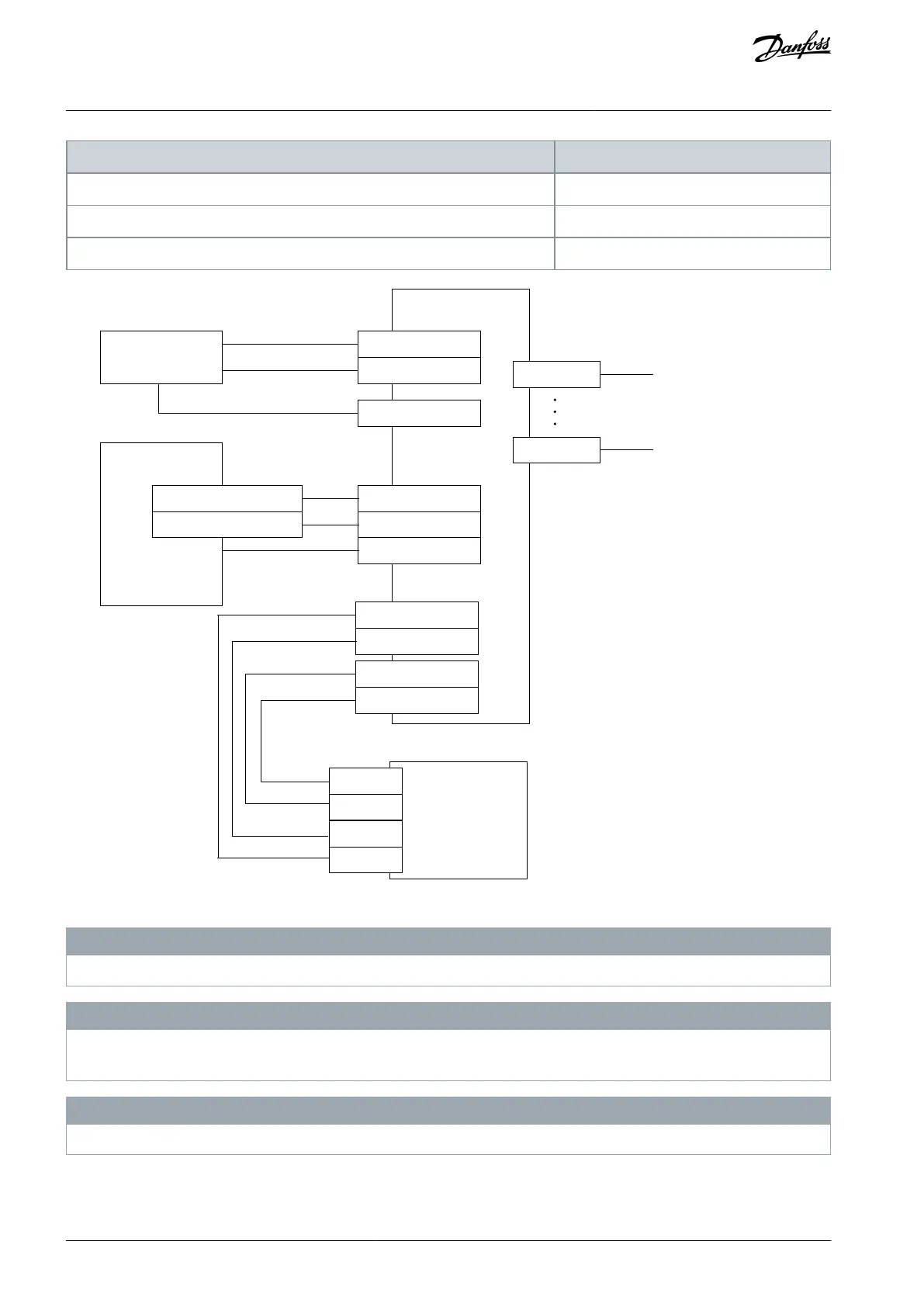
Control switch
Door lock
control
/PLC
controlling the
locks
Common ground
SLS 1
X4-13 (DIN2A)
X4-14 (DIN2B)
X7-1
X3-9 (+24V)
X3-5 (OUT1A)
X3-6 (OUT1B)
Door lock control 1
Door lock control 2
X3-10 (GND)
Advanced safety
option board
Encoder input
connections
X7-8
X3-1 (STO 1)
X3-2 (STO 2)
STO
option board
OPTAF
STO
X3-3 (GND)
X3-4 (GND)
SD2+
SD1+
SD2-
SD1-
e30bi383.10
Illustration 82: An Output with SLS Reached used for Door Control
N O T I C E
This example does not consider the source of the SLS request. Additional devices and connections may be required.
N O T I C E
There should be an access behind the door when there is a power loss or a fault in the option board. Prevent the possibility of
being trapped.
N O T I C E
In this configuration, the door will be locked again if SLS monitoring is violated. Prevent the possibility of being trapped.
AQ319736045637en-000101 / DPD01798184 | Danfoss A/S © 2021.06
Configuration Examples
VACON® NXP Advanced Safety Options
Operating Guide