•
•
•
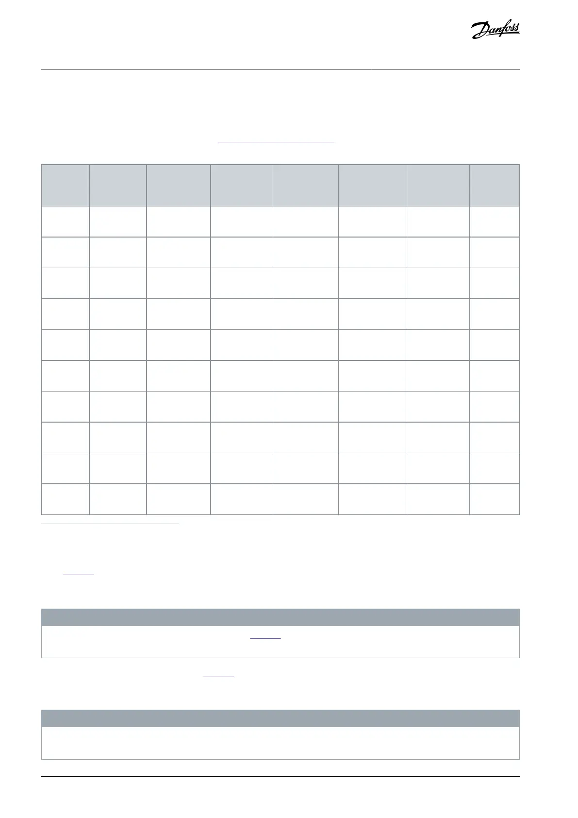
PFH
Category
Performance level
For the diagnostic coverage for the encoder, see 3.6.6 Encoder Signal Verification.
Table 11: Achievable Safety Levels when Using Speed Sensors without Certificate
Digital Pulse +
estimated
speed
Proximity sen-
sor + estima-
ted speed
Sin/Cos + prox-
imity sensor
Digital Pulse +
proximity
sensor
1
Only if the monitored limits to both directions are set to the same value or both values are greater than the value of Allowed Deviation of Speed
Sources.
2
Only if the monitored limits to both directions are set to the same value.
Table
Table 11 gives the maximum SIL, PL, and Cat levels that can be achieved with a combination. Other factors than speed meas-
urement can be the limiting factor on system level. For example, either SIL 2 or SIL 3 can be achieved with the OPTAF STO option
board as a single final element. See the VACON
®
NX OPTAF STO Board Manual for further information.
N O T I C E
For non-safe Sin/Cos encoders, it is required in the table Table 11 that the encoder is implemented in analog design. The fault
model "Exchange of Sin and Cos signal inside the encoder" must be excluded.
Combinations that are not listed in the table Table 11 are not tested or supported, and offer no increase to the claimed safety levels.
It can still be possible to use unlisted combinations. Regardless of the used speed measurement combination, it is the responsibility
of the system designer to make sure that the used combination is adequate and sufficient.
N O T I C E
When multiple speed sources are used, the monitored limit of a safety function must not be set below the value of Allowed Devi-
ation of Speed Sources.
AQ319736045637en-000101 / DPD0179834 | Danfoss A/S © 2021.06
Overview of the System
VACON® NXP Advanced Safety Options
Operating Guide