Table 3. DD9410 system with DS600 racking locations
Component Configuration Rack location
Controller location with DS600
shelves
Single node or HA primary node U10-U11
HA standby node U13-U14
FS240 location with DS600
shelves
HA U24-U25
DS600 locations Single node or HA U02-U09, U16-U23
Table 4. DD9910 system with DS600 racking locations
Component Configuration Rack location
Controller location with DS600
shelves
Single node or HA primary node U10-U11
HA standby node U13-U14
FS240 location with DS600
shelves
HA U32-U33
DS600 locations Single node or HA U02-U09, U16-U31
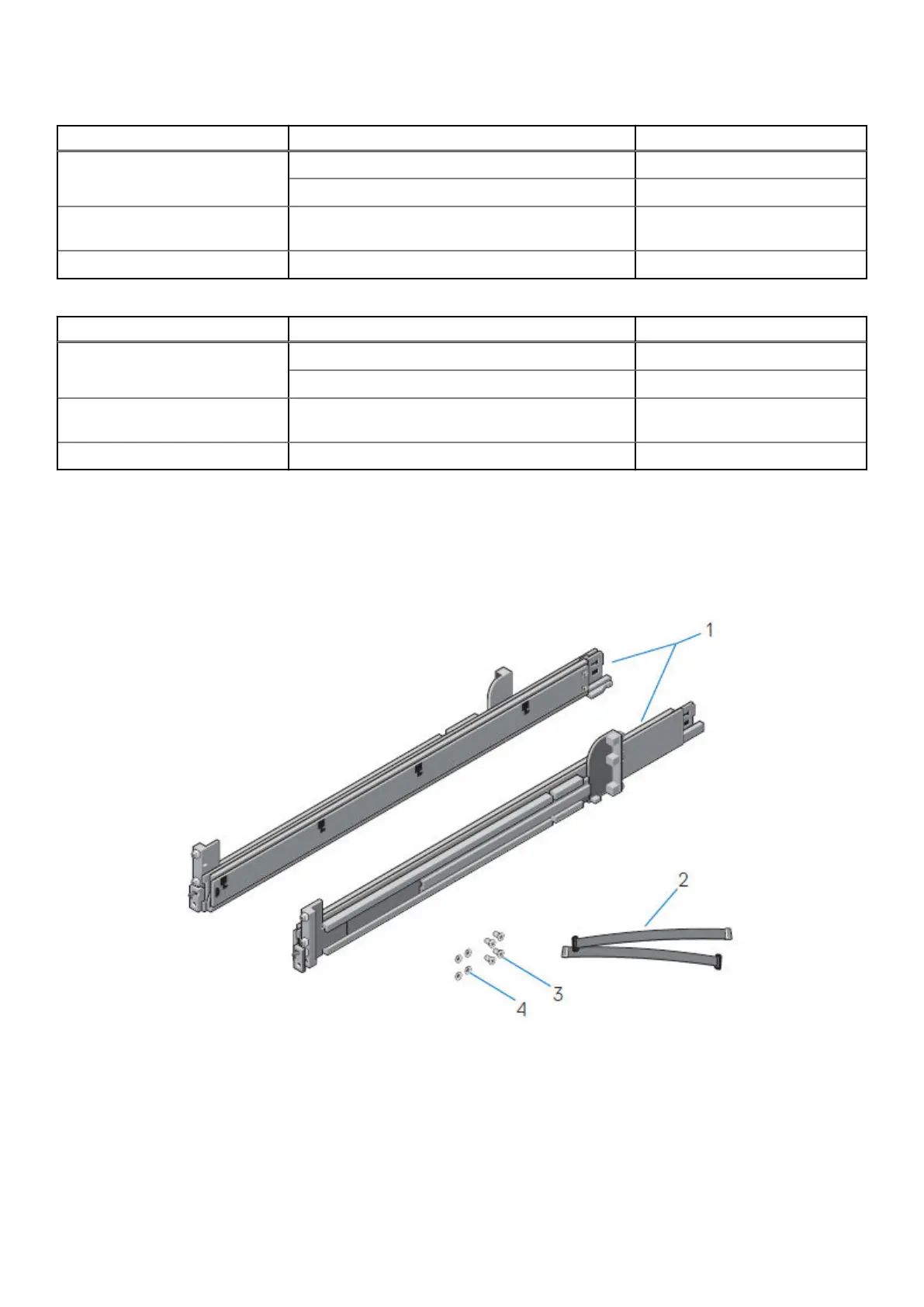
Identifying the rail kit components
This section describes the steps to identify the rail kit components.
The 2U sliding rail assemblies allow the server to be secured in the cabinet, and extended from the cabinet so that the system
cover can be removed to access the internal FRUs.
Figure 5. Sliding rail assembly - 2U systems
1. Sliding rail (2)
2. Velcro strap (2)
3. Screw (4)
4. Washer (4)
The rails are compatible with racks with square holes, unthreaded round holes, and threaded round holes.
18
Install the System in the Rack