25
Installation and Operation Manual for RPI M50A
5 Planning the installation
5.7 AC connection
Always adhere to the specic regulations applicable in
your country or region.
Always adhere to the specic regulations dened by
your grid operator.
For the safety of the user and for the security of your instal-
lation, install required safety and protection devices that
are applicable for your installation environment (example:
automatic circuit breaker and/or overcurrent protection
equipment).
2
Use the proper upstream circuit breaker to protect the
inverter:
Model Upstream Circuit Breaker
RPI M50A 100 A
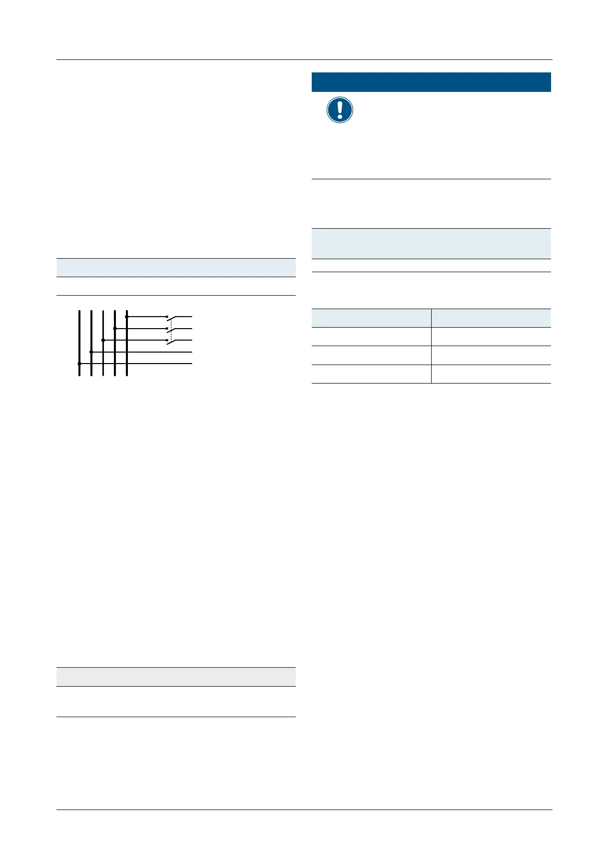
G N L1 L3L2
N
L1
L2
L3
PE
To solar inverter AC
plug
Fig. 5.12: Where to place upstream circuit breakers
in the system
The inverter is not capable of feeding in DC residual cur-
rents due to its design. It fullls this requirement in accor-
dance with DIN VDE 0100-712.
The possibilities of faults were examined by Delta
without taking the integrated RCMU (residual-current
monitoring unit) into account. When examining
these faults in terms of the current valid installation
standards, no danger in combination with a type A
upstream residual-current device (RCD) can occur.
Therefore faults that would otherwise require the use
of a type B residual-current device due to the inverter
can be excluded.
The integrated all-pole sensitive RCMU is certied
according VDE 0126 1-1/A1:2012-02 §6.6.2 for a trip-
ping current of 300 mA. RCD Type A can be used for
this inverter, according to the following table.
M50A
Minimum tripping current of the
RCD
mA ≥300
NOTE
The value of the tripping current mainly
depends on the quality of the solar
modules, the size of the PV array and
environmental conditions (e.g. humid-
ity). The tripping current of the residual
current device must not be less than
the specied minimum tripping current.
Permitted earthing systems
Earthing
System
TN-S TN-C TN-C-S TT IT
Permitted Yes Yes Yes Yes No
AC grid voltage requirements
3P3W 3P4W
L1-L2 400 V
AC
± 20% L1-N 230 V
AC
± 20%
L1-L3 400 V
AC
± 20% L2-N 230 V
AC
± 20%
L2-L3 400 V
AC
± 20% L3-N 230 V
AC
± 20%

 Loading...