40
ASSEMBLING INSTRUCTIONS - LIQUID INCORPORATION SYSTEM
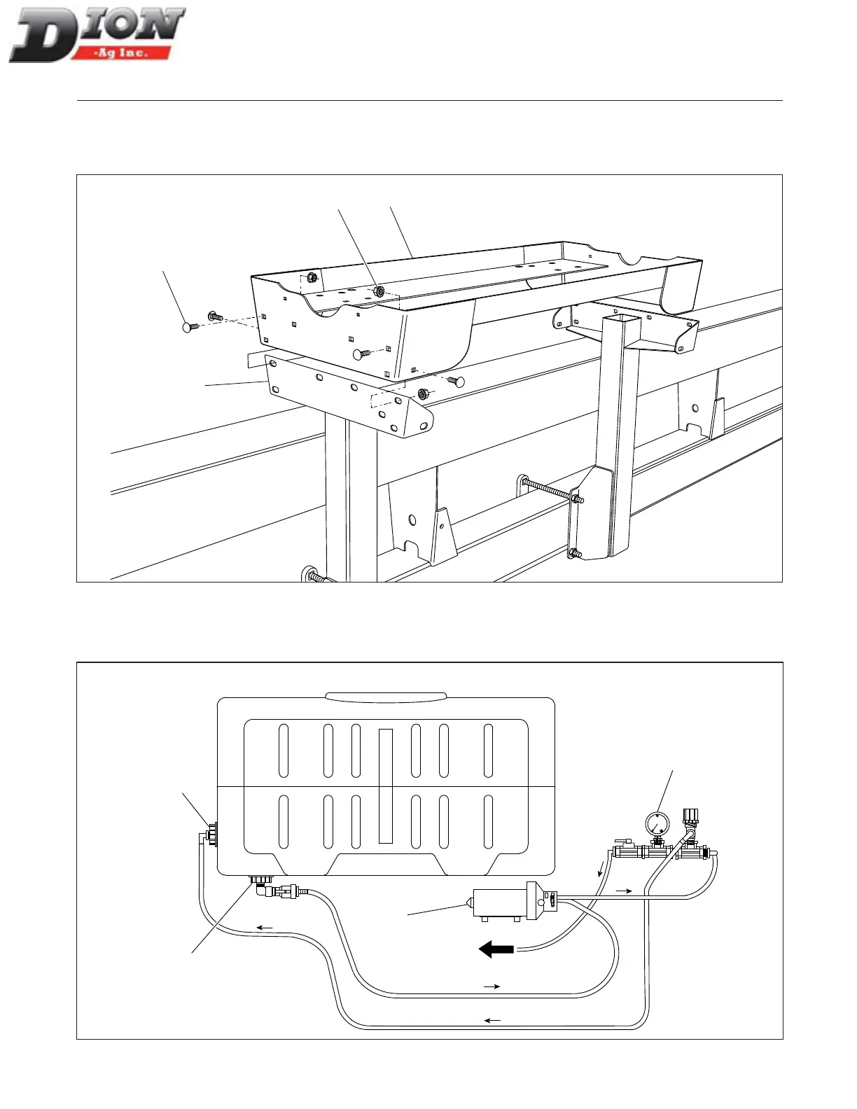
STEP 2
Install the tank support assembly (item 6). Secure it in place with sixteen 3/8” x 1” lg carriage bolts (item 7) and six-
teen 3/8” ange nuts (item 8). Adjust the front support bracket position (item 1) with the support assembly (item 6).
6
8
7
1
Figure 28 Installing the tank support assembly
The diagram below shows the components and the ow direction of the liquid incorporation system with one tank.
Use it to identify the components installed in steps 3 to 16.
Towards
Forage
Harvester
Return fitting
(step 9)
Pressure gauge
assembly
(step 6)
Outlet
fitting
(step 8)
Pump
(step 3)
FRONTREAR
Pump
Figure 29 Tank installation diagram
Manual No. F4117E987E V1.1