41
ASSEMBLING INSTRUCTIONS - LIQUID INCORPORATION SYSTEM
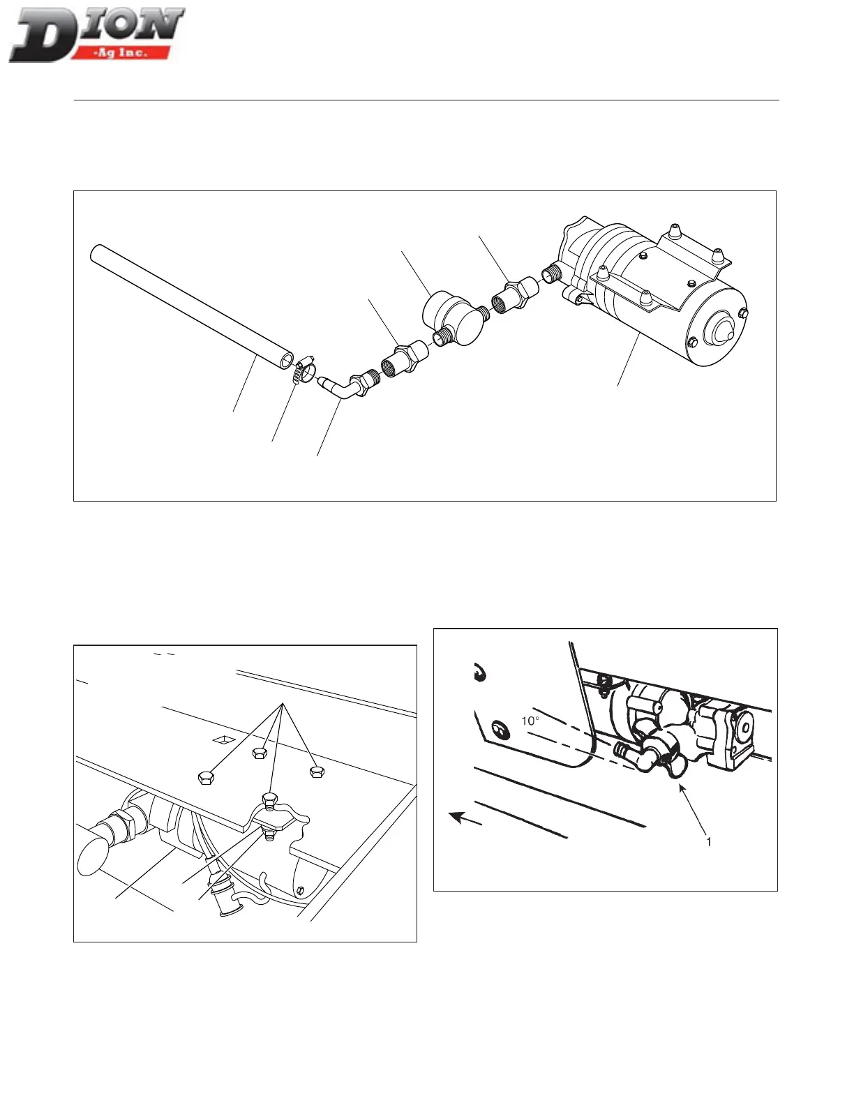
STEP 3
Connect the two adaptors (item 6) to the lter (item 1) with the water ow arrow towards the pump (item 2). Install
the 18 1/2” lg (47cm) hose (item 3) with a 90-degree elbow (item 4) on the adaptor. Use a hose clamp (item 5) and
tighten properly. Do not connect the other end of the hose yet.
1
6
2
4
3
5
6
Figure 30
STEP 4
Secure the pump (item 1) under the tank bottom on the
left hand side with four 1024 X 1 1/2” lg hex hard bolts
(item 2) and four lock nuts (item 5). Tighten nuts until the
rubber spacers are lightly compressed.
2
1
6
5
Figure 31 Installing the pump
STEP 5
Screw the wing elbow (item 1) on the pump outlet and
direct the elbow tip forward with an angle of approximate-
ly 10 degrees upward.
Figure 32
NOTE: The heads of the
bolts (item 2) must be on
top as shown here.
TOWARDS TRACTOR
Manual No. F4117E987E V1.1