42
ASSEMBLING INSTRUCTIONS - LIQUID INCORPORATION SYSTEM
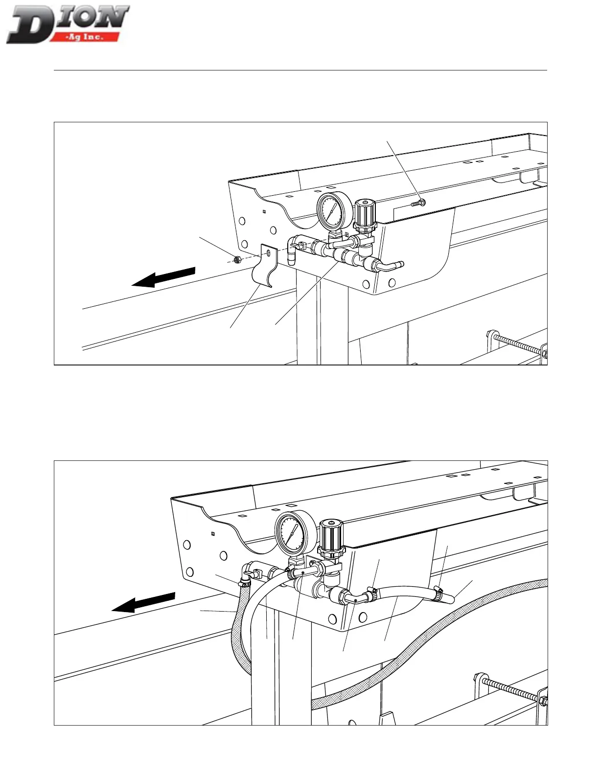
STEP 6
Secure the pressure gauge assembly (item 1) to the tank support at the front with and a clamp (item 2) and a 1/4”
x 1 1/4” lg carriage bolt (item 2). Tighten the self-locking nut properly (item 4).
1
2
4
3
Figure 33 Installing the pressure gauge assembly (pre-assembled)
STEP 7
Install a 9” lg (23cm) hose on the pump elbow (item 2) and on the pressure gauge elbow (item 3) with two hose
clamps (item 4) then tighten properly. Install a 61” lg (155 cm) return hose (item 5) on the pressure gauge elbow
(item 6) with one hose clamp (item 4). Finally, install the /8” dia. X 264” lg (670cm) feed hose (to the Forage Har-
vester) (item 7) with one hose clamp (item 4) then tighten properly.
1
3
5
6
7
4
4
4
2
Figure 34 Connecting the hoses
TOWARDS TRACTOR
TOWARDS TRACTOR
Manual No. F4117E987E V1.1