43
STEP 8
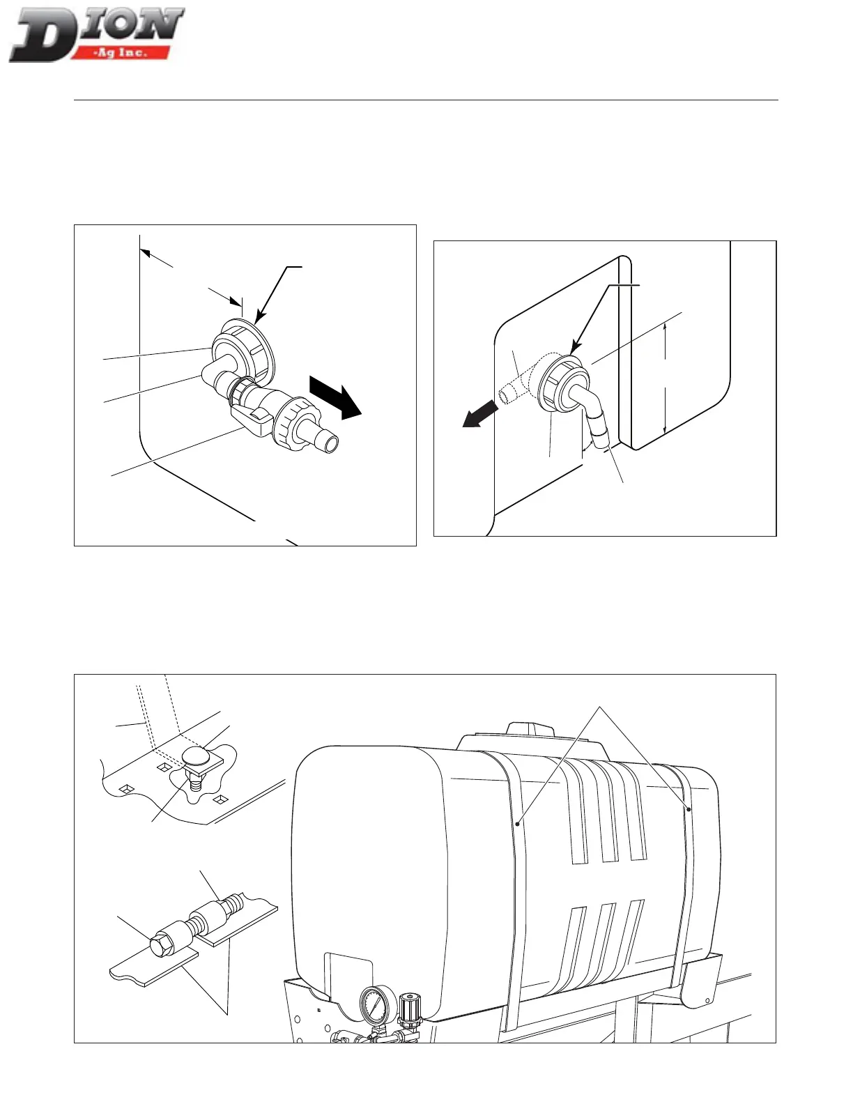
Install the outlet tting (item 1) in the center, underneath
the tank, with a 90-degree elbow (item 2), a ball valve
(item 3) aimed towards the front of the tank with an an-
gle of approximately 15 degrees to the right. Aim the
valve outlet towards the tractor.
3
2
1
5”
(13 cm)
Figure 35 Installing the outlet tting
STEP 9
Install the return bulkhead tting (item 1) at the rear
of the tank along with one a 90-degree elbow (item 2)
aimed downward at an angle of approximately 15 de-
grees to the right. Install a 90-degree elbow (item 3) in-
side the tank and aim it to the left bottom corner (see
arrow). Tighten the bulkhead tting properly
15
o
2 3/4”
2
1
3
Figure 36 Installing the return tting
Drill 1 5/8”
hole in the
center
Drill 1 5/8”
hole in the
center
NOTE: The heads of the
bolts (item 2) must be on
top as shown here.
ASSEMBLING INSTRUCTIONS - LIQUID INCORPORATION SYSTEM
TOWARDS
TRACTOR
UNDERNEATH TANK
BEHIND TANK
STEP 10
Bolt the four steel bands (item 1) on the tank with four 3/8” x 3/4” lg carriage bolts (item 2) as shown and tighten the
nuts properly. Install the tank with the return line at back (see step 11). Tighten the steel bands with two 3/8” x 5 1/4”
lg hex. bolts (item 5) and two self-locking nuts (item 6)..
1
1
1
2
3
5
6
Figure 37 Installing the tank
Manual No. F4117E987E V1.1