49
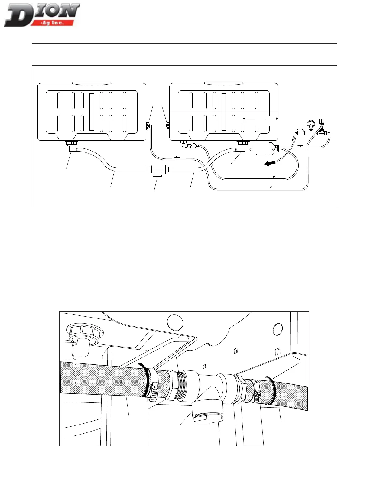
The diagram below shows the components and the ow direction of the liquid incorporation system with two tanks.
Use it to identify the components installed in steps 19 to 21.
12”
(30 cm)
Towards
Forage
Harvester
Pump
1
3
2
5
6
7
4
FRONTREAR
Figure 48
STEP 19
Drill a hole in the front tank, 12” (30cm) from the front, at the center. Use a 2 5/8” dia. hole saw. Install the adaptor
(item 1 in gure 21). Tighten properly.
STEP 20
Install the 1 1/2” X 25” lg hose assembly (items 4 and 5) linking both tanks together. Use tie-wraps to secure both
hoses. This system keeps the liquid level equal between both tanks. It also keeps the mix homogeneous. The «T»
connector (item 3) between both hoses is equipped with a drain plug to empty both tanks, when necessary.
NOTE: Before putting away the machine for winter, make sure to completely drain the system in order to avoid any
break downs caused by freezing.
4
5
3
Figure 49 Installing the hose assembly between tanks
ASSEMBLING INSTRUCTIONS - LIQUID INCORPORATION SYSTEM
FRONT REAR
Manual No. F4117E987E V1.1