162 ECLYPSE APEX
Typical Modbus RTU
Device
2'-5 1/4"
Typical Modbus RTU
Device
Typical Modbus RTU
Device
Data Bus: Shielded Twisted Pair Cable
Typical Modbus RTU
Device
Data Bus Shields:
Connect to the ‘S’
Terminal
Electrical
System
Ground
The shield of the data bus must be connected to
the electrical system ground at one point only –
usually at the Building Controller, when present
NET-
NET +
S
NET-
NET +
S
NET-
NET +
S
NET-
NET +
S
RS-485
-
+
S
ECLYPSE
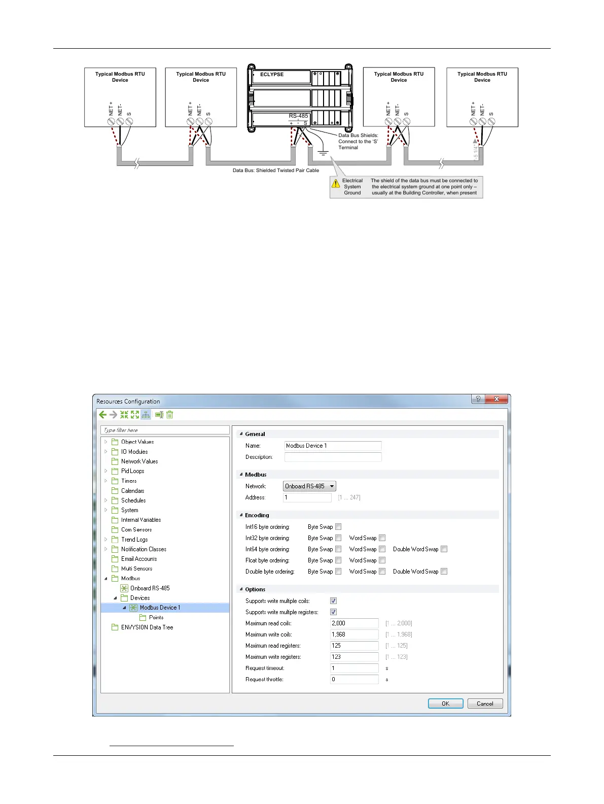
Figure136: Typical Cable-Shield Grounding Requirements for a Modbus RTU Data Bus Segment with an
ECLYPSE Controller located in the Middle of the Data Bus
Device Addressing
Device addressing allows the coordinated transfer of messages between the master (the ECY Series
Controller) and the slave Modbus RTU device. For this, each device connected to the Modbus RTU
data bus is identified by its address.
About the Device Address
Each slave device must have its own unique address number in the range from 1 to 247.
Refer to the device’s hardware installation guide for information about how to set its address number.
Set the Modbus device parameters with EC-
gfx
Program in the
Resources Configuration
window,
Mod-
bus Device
block.
Figure137: Setting the Modbus Device Parameters in EC-gfxProgram’s Resources Configuration Window
See the EC-
gfx
Program User Guide for more information.
Modbus RTU Communication Data Bus Fundamentals