Rev 0.1
Dr.coffee Service Manual 12
4 Schematic Circuit
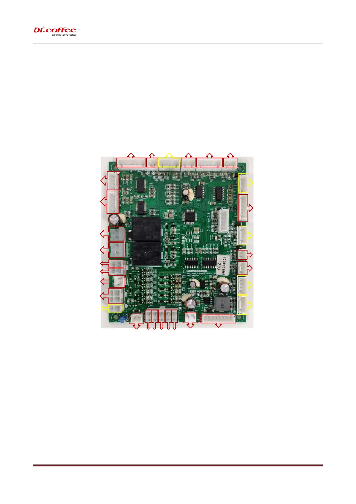
4.1 M12 Main control board circuit
Pressure relief valve stepper motor
Transmission motor
Connection line
RGB Light board connection line
Automatic water inlet valve group
connection line
Reserved fridge light connection line
Drip tray detection reed pipe connection line
Water level detection PCB connection line
Reserve milk detection interface
Pressure relief solenoid valve line
Hot water bypass valve line
Hot water and coffee valve line
Main control board communication line
Water full detection cable
Grinding Hall connection line
Flowmeter connection line