3. WP8010 INSTALLATION
D-306233 CUSDOC PM-10/30 V18 DSC TRIPLE EN INST 19
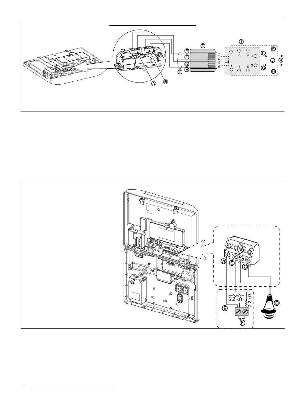
PHONE WIRING IN NORTH AMERICA
A. LINE
B. SET
C. RJ-31X cord
D. 8-position RJ-31X plug
E. Brown
F. Red
G. Green
H. Gray
I. RJ-31X jack
J. Line from street
K. House phones
Figure 4.3b – Phone Wiring in North America
Phone wiring in the UK: Line terminals must be connected to pins 2 and 5 of the wall jack.
For all installations: If DSL service is present on the phone line, you must route the phone line through a DSL filter
(refer to MESSAGE TO THE INSTALLER on page 2 for further details).
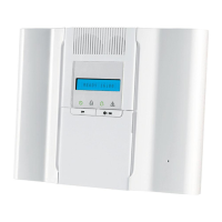
4.4 Connecting Wired Zone and Siren
(detail "B" in Figure 4.1)
If an expander module is not used, one wired zone and one low voltage siren can be connected directly to the front
panel PCB (not allowed in UL installations).
WIRED ZONE
1
&SIREN WIRING
A. GND
B. Wired Zone
C. Siren*
D. Site external siren MG electronics
MG441PDS or equivalent 6-
12VDC, 150 mA Max*
E. Magnetic contact or any other
contact (not a detector)
F. Alarm N.C.
*Not to be used in UL Listed Product
Figure 4.4 – Wired Zone and Siren Wiring
4.5 System Planning & Programming
Program the system now as instructed in the programming section.
The tables in APPENDIX C will help you plan and record the location of each detector, the holder and assignment of
each transmitter.
Wired zones can be enrolled in any zone in the WP8030 control panel from 01 to 64