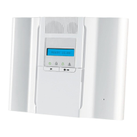
3. WP8010 INSTALLATION
D-306233 CUSDOC PM-10/30 V18 DSC TRIPLE EN INST 63
5.8.3 Voice Box Mode
This mode allows you to determine whether two-way voice communication is to be sounded either via an external
speakerphone, via the control panel, or via both.
For the two-way voice communication procedure, follow the instructions below. Additional details and guidance are
provided in section 5.2.
06:CUSTOM NAMES
VOICE BOX MODE
Enter "VOICE BOX MODE", and then refer to the table below which provides you with the options.
Define whether two-way voice communication is to be sounded either via the external
speakerphone ("VOICE BOX ONLY"), via the control panel ("NO VOICE BOX"), or via both
("VOICE BOX MIXED").
Options: NO VOICE BOX; VOICE BOX ONLY and VOICE BOX MIXED (default)
5.9 Diagnostics
5.9.1 General Guidance – "Diagnostics" Flow-Chart & Menu Options
The DIAGNOSTICS menu enables you to test your system and to verify proper operation of your WP8010/WP8030
panel, wireless devices attached to it and the communication (GSM/GPRS/SIM) modules.
IMPORTANT! Reliable reception must be assured during the initial testing and also throughout subsequent system
maintenance. A device should not be installed in location where signal strength is "poor". If you get "poor" signal
strength from a certain device, simply re-locate it and re-test until a "good" or "strong" signal strength is received. This
principle should be followed throughout the diagnostic test procedure.
Note: For UL installations, "strong" signal strength for WL Devices is required.
The diagnostic test process is shown below.
The "07.DIAGNOSTICS" menu contains several sub-menu options, each covering a group of configurable features and
parameters related to the communication and reporting as follows (see the list in Step 3 of the chart below):
Description of Option Features and Parameters
Describes how to test the devices attached to the WP8010/WP8030 panel, review
devices' status and RF signal status. You can test all devices, test single device,
review devices status and review RF problems, in case of any.
Describes how to test the GSM/GPRS communication module.
Tests the SIM number to ensure correct entry of the SIM number in the control
panel.
Enables to test the communication of the Broadband Module with the
PowerManage server.
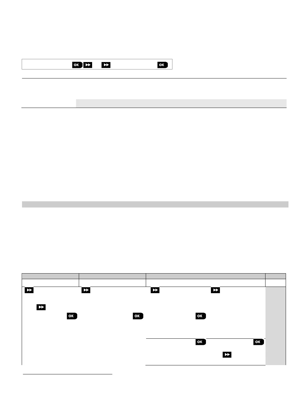
To enter the "07.DIAGNOSTICS" menu and to select and configure an option, proceed as follows:
Select the diagnostics you want to perform
Contact sensors
Motion sensors
Repeaters
Refers to WP8030 with voice option only
SIM number test is not applicable for UL installations
Broadband is not applicable for UL installations
The name of the product is PowerLink3 IP Communicator