3. WP8010 INSTALLATION
D-306233 CUSDOC PM-10/30 V18 DSC TRIPLE EN INST 23
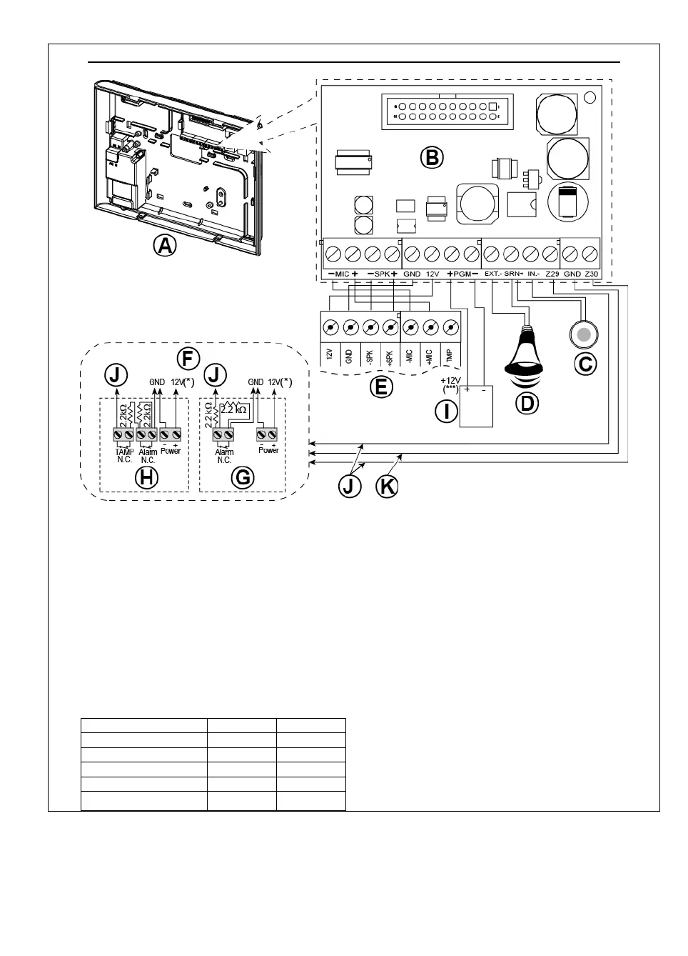
OPTIONAL EXPANDER MODULE, ZONES, SIRENS, AUDIO BOX AND WIRED DETECTORS WIRING
A. Back Unit
B. Expander
C. Internal siren or strobe 6-12 VDC,
150 mA Max.
D. External siren MG441PDS or similar siren 12 VDC
(nominal) 350 mA Max.
E. Voice box
F. Connect wired detectors as illustrated.
Note:
The wired detector should be installed at least 2
meters away from the control panel.
Regarding the two wired zones, the control panel
classifies the events according to the resistance it
measures as shown in the table below.
E.O.L or Arming Key Resistance
Notes:
1. The E.O.L resistors are 2.2 kΩ resistors of 1/4 W,
5% supplied with the panel and are UL listed
under the name EOLR-3, kit number 57000850.
2. If the Arming enabled is set, the wired zone must
be located in the protected area.
G. Detector without tamper switch or Arming Key (see
section 5.4.2, “Zone Type List” table).
H. Detector with tamper switch or arming key's tamper
I. PGM device
J. Wired zone A or B
K. Ground (GND)
Figure 4.9b – Zone
and Siren Wiring
 Loading...