Thread cutter
68 Service Manual 867 Version 02.0 - 04/2015
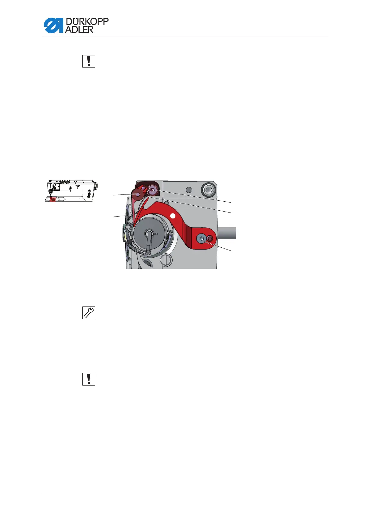
Screw the four setscrews (2) tightly in place on the clamping ring (1)
before you loosen the setscrews (5). The clamping ring (1) and control
cam (4) are both mutually used as a stop and should not be undone at
the same time.
4. Loosen the setscrews (5).
5. Press the actuating lever (7) against the solenoid (9).
6. Turn the control cam (4) such that its widest extent (6) is at the top, next
to the roller (3).
7. Move the control cam (4) such that the distance between its widest
extent (6) and the roller (3) is 0.1 mm at most.
8. Tighten the setscrews (5).
9. Loosen the clamping screw (8) on the actuating lever (7).
Fig. 56: Aligning the thread-pulling knife sideways - Part 2
10.Turn the thread-pulling knife (12) such that the circle mark is exactly
next to the tip of the counter-blade (11).
11.Tighten the clamping screw (8) on the actuating lever (7) such that the
actuating lever (7) has no axial play.
12.Loosen all four setscrews (2) on the clamping ring (1).
13.Push the clamping ring (1) to the right as far as it will go and against
the control cam (4).
14.Check the loop stroke position ( page 45).
15.Tighten all four setscrews (2) on the clamping ring (1).
<
0
,
.
+
^
(10) - Screw
(11) - Counter-blade
(12) - Thread-pulling knife
(13) - Screw
(14) - Hook thread clamp
(15) - Screw

 Loading...