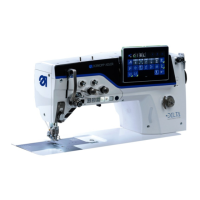
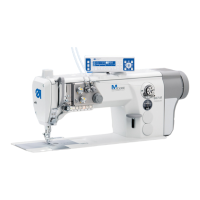
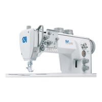
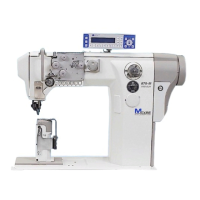
Machines with integrated motor
Service Manual 867 Version 02.0 - 04/2015 91
19.3 Assembling the drive
Attaching
the rotor
Fig. 76: Attaching the rotor
1. Push the rotor (3) onto the shaft until the deep groove ball bearing is
resting against the stop.
2. Screw all four threaded screws (1, 2) firmly in place, observing the sur-
face of the shaft in doing so: Screw the first screw in the direction of
rotation firmly in place on the surface.
(1) - Threaded screw
(2) - Threaded screw
(3) - Rotor with deep groove ball bearing
①
②
③
 Loading...


