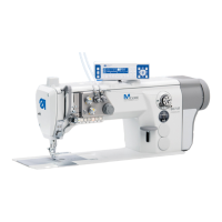
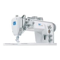
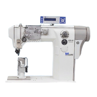
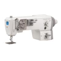
Machines with integrated motor
Service Manual 867 Version 02.0 - 04/2015 95
Attaching
the handwheel
flange
Fig. 81: Attaching the handwheel flange
1. Attach the handwheel flange (1) such that the two markings (2, 3) are
in line.
2. Tighten both setscrews (4), taking care in doing so that there is a dis-
tance of approx. 0.5 - 1 mm between the handwheel flange (1) and
cover plate.
Attaching
the handwheel
Fig. 82: Attaching the handwheel
1. Attach the handwheel (1) and tighten all three screws (2).
2. Set the zero point via the control, see manual for the control unit.
(1) - Handwheel flange
(2) - Cover marking
(3) - Marking for handwheel flange
(4) - Setscrews
②
①
④
③
(1) - Handwheel (2) - Screws
②
①

 Loading...

