Machine description
4812165301.pdf 2022-09-02
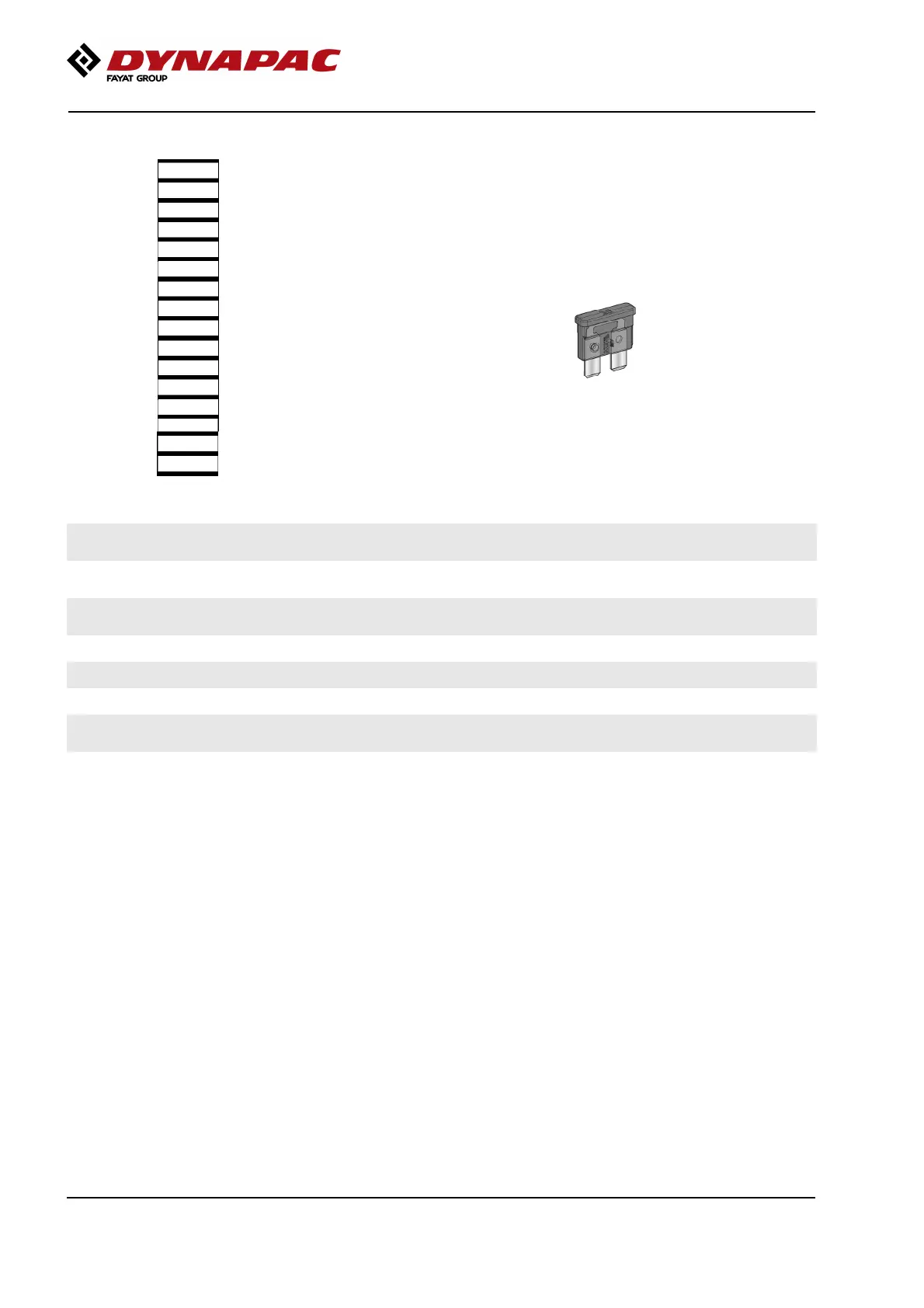
Fuses in the main switchbox.
Fig. Fuses
1
2
3
4
5
6
7
8
9
10
11
12
13
14
15
16
The figure shows the position of the fuses.
The table below gives fuse amperage and function. All
fuses are flat pin fuses.
1. Main relay, 24V outlet engine
compartment
10A 9. After treatment system, diesel engine 15A1. Main relay, 24V outlet engine
compartment
10A 9. After treatment system, diesel engine 15A
2. ECU, Outlet boot loading, I/O board,
display
5A 10. DEF Supply module 15A2. ECU, Outlet boot loading, I/O board,
display
5A 10. DEF Supply module 15A
3. ECU PWR1, Speed sensor 10A 11. 12V outlet, Radio, 24/12V converter,
gateway Dyn@lyzer
10A3. ECU PWR1, Speed sensor 10A 11. 12V outlet, Radio, 24/12V converter,
gateway Dyn@lyzer
10A
4. ECU PWR2, Forward/Reverse lever 10A 12. GPS, DCM, DCO, tilt sensor 10A4. ECU PWR2, Forward/Reverse lever 10A 12. GPS, DCM, DCO, tilt sensor 10A
5. ECU PWR 3 20A 13. Reserve5. ECU PWR 3 20A 13. Reserve
6. ECU PWR 4 20A 14. Dyn@lyzer 10A6. ECU PWR 4 20A 14. Dyn@lyzer 10A
7. 24V outlet operator's station,
Tachograph lights
10A 15. Indicator relay 7.5A7. 24V outlet operator's station,
Tachograph lights
10A 15. Indicator relay 7.5A
8. Hydraulic/Fuel sensor, Engine 10A 16. Driving lights 10A8. Hydraulic/Fuel sensor, Engine 10A 16. Driving lights 10A
60