Machine description
4812165301.pdf2022-09-02
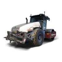
Fuses at the master switch.
Fig. Cover, left side
1. Fuse box
2. Batteries (x2)
3. Battery disconnector plate
1
3
2
The fuse box (1) is located inside the cover by the
steps on the left-hand side of the roller.
This is also where the batteries (2) are, and the starter
relay (4) and preheating relay (5) and fuses (6, 7) are
placed behind the battery disconnector plate (3).
6
7
5
4
4. Starter relay
5. Preheating relay
6. Fuse, engine-ECU (30A) (F13)
7. Fuse (10A) (F23)
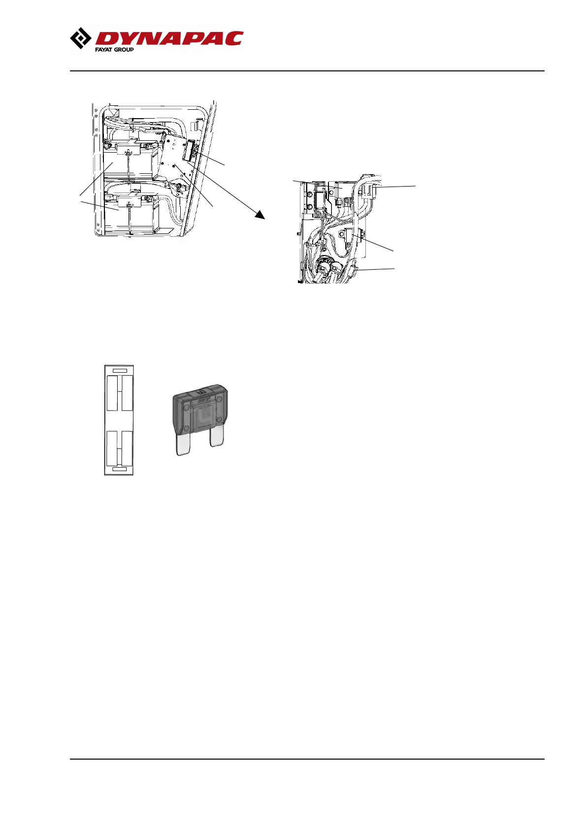
Fuse box at master switch
Fig. Fuse box (F4), master switch.
1
3
2
4
The figure shows the position of the fuses.
The amperage and function of the fuses are shown
below. All fuses are flat pin fuses.
F4.1 Main fuse 50AF4.1 Main fuse 50A
F4.2 Cab 30AF4.2 Cab 30A
F4.3 -F4.3 -
F4.4 Grid heater 100AF4.4 Grid heater 100A
61