EasyManuals Logo

Eaton EASY-E4 Series User Manual

Eaton EASY-E4 Series
621 pages
To Next Page IconTo Next Page
To Previous Page IconTo Previous Page
Page #205 background imageLoading...
Page #205 background image
6. Function blocks
6.1 Manufacturer function blocks
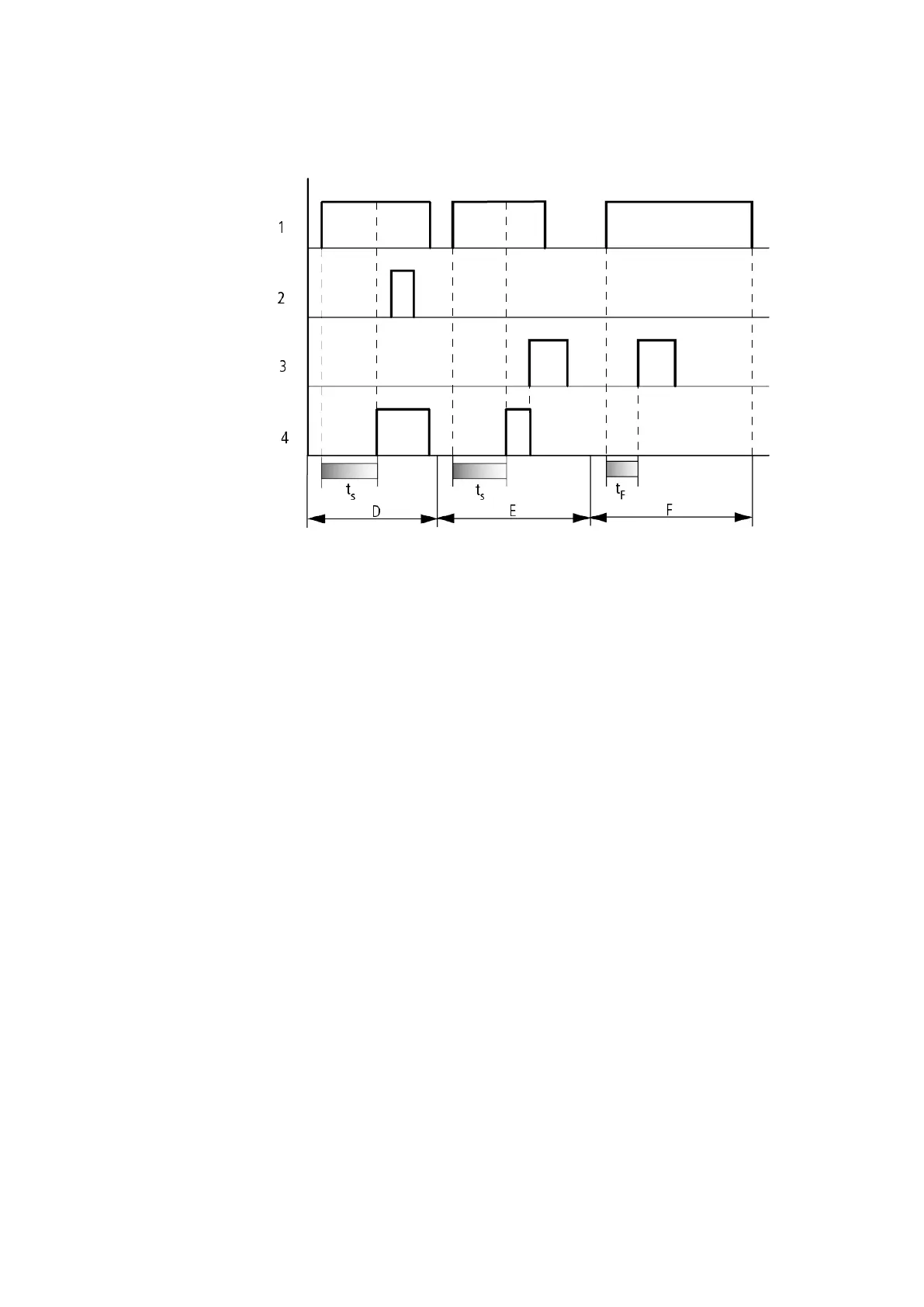
Figure 115: Signal diagram of timing relay, on-delayed (with and without random switching)
Range D: The stop coil is inoperative after the time has elapsed.
Range E: The reset coil resets the relay and the contact.
Range F: After the reset coil is activated, the switching contact is switched off and the internal time
counter is reset. The function relay waits for a new trigger pulse.
How the timing relay works with the off-delayed operating mode with and without
random times
Random switching, with and without retriggering
The contact of the timing relays switches randomly within the SETPOINT value range.
Retriggering
When the time is running and the trigger coil is reactivated or deactivated, the ACTUAL
value is reset to zero. The SET time of the timing relay is timed out once more.
easyE4 11/18 MN050009 EN www.eaton.com
201

Table of Contents

Other manuals for Eaton EASY-E4 Series

Questions and Answers:

Question and Answer IconNeed help?

Do you have a question about the Eaton EASY-E4 Series and is the answer not in the manual?

Eaton EASY-E4 Series Specifications

General IconGeneral
TypeProgrammable Relay
Digital InputsUp to 12
Digital OutputsUp to 8
DisplayLCD
Operating Temperature-25°C to +55°C
Protection DegreeIP20
Storage Temperature-40°C to +70°C
Supply Voltage24 V DC, 100-240 V AC
Analog Inputs4
OutputsRelay, transistor
ProgrammingEASY-SOFT-PRO
CommunicationEthernet, Modbus, CANopen
ExpansionExpandable with additional modules
Relative Humidity5% to 95% (non-condensing)
StandardsIEC/EN 61131-2, UL 508, CSA C22.2 No. 142

Related product manuals