EasyManuals Logo

Eaton EASY-E4 Series User Manual

Eaton EASY-E4 Series
621 pages
To Next Page IconTo Next Page
To Previous Page IconTo Previous Page
Page #132 background imageLoading...
Page #132 background image
5. Programming on the device
5.3 Circuit diagram elements
"Set" S and "Reset" R coil functions
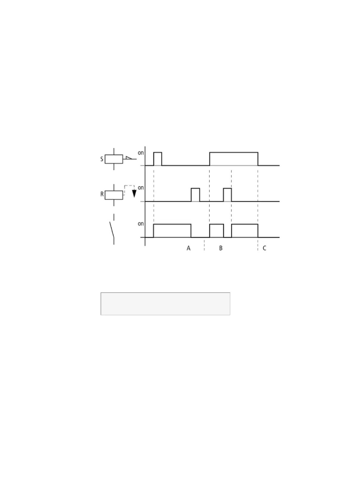
The Set S and Reset R coil functions are normally used in pairs.
The relay picks up when the coil is set (A) and remains in this state until it is reset (B)
by the coil function.
The power supply is switched off (C), the coil is not retentive.
Figure 72: Set and Reset signal diagram
If both coils are triggered at the same time, priority is given to the coil further down in
the circuit diagram. This is shown in the above signal diagram in section B. Has a higher
rung number(The Reset coil in the example above.)
I 05---------------S Q 01
I 10---------------R Q 01
Figure 73: Simultaneous triggering of Q 01
The above example shows the Reset coil with priority when the Set and Reset coil are
triggered at the same time.
128
easyE4 11/18 MN050009 EN www.eaton.com

Table of Contents

Other manuals for Eaton EASY-E4 Series

Questions and Answers:

Question and Answer IconNeed help?

Do you have a question about the Eaton EASY-E4 Series and is the answer not in the manual?

Eaton EASY-E4 Series Specifications

General IconGeneral
TypeProgrammable Relay
Digital InputsUp to 12
Digital OutputsUp to 8
DisplayLCD
Operating Temperature-25°C to +55°C
Protection DegreeIP20
Storage Temperature-40°C to +70°C
Supply Voltage24 V DC, 100-240 V AC
Analog Inputs4
OutputsRelay, transistor
ProgrammingEASY-SOFT-PRO
CommunicationEthernet, Modbus, CANopen
ExpansionExpandable with additional modules
Relative Humidity5% to 95% (non-condensing)
StandardsIEC/EN 61131-2, UL 508, CSA C22.2 No. 142

Related product manuals