5. Programming on the device
5.3 Circuit diagram elements
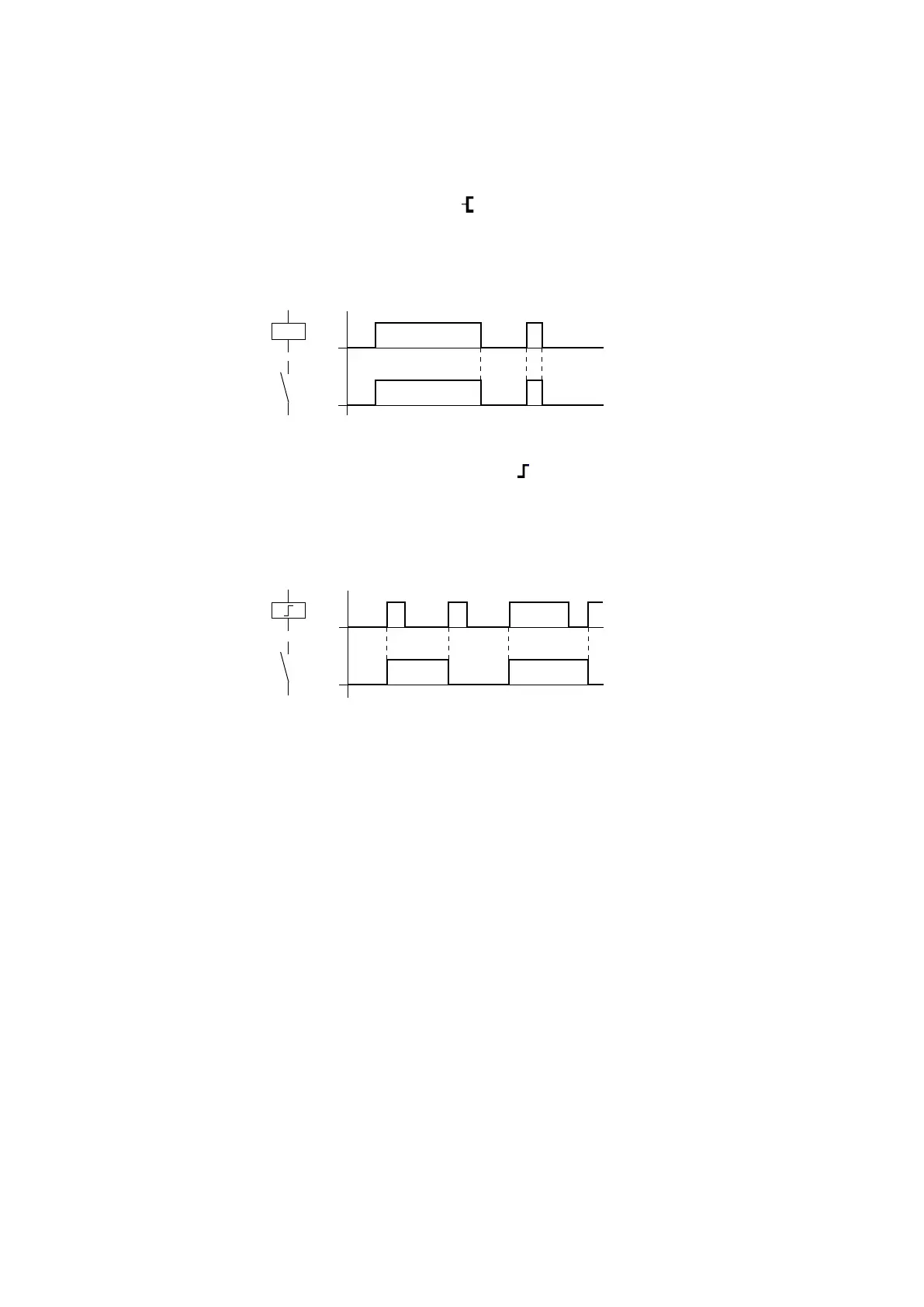
Coil with contactor function
The output signal follows the input signal directly, the relay operates as a contactor.
Fig. 96: Contactor function signal diagram
Coil with the impulse relay function
The relay coil switches whenever the input signal changes from 0 to 1. The relay
behaves like a bistable flip-flop.
Fig. 97: Impulse relay signal diagram
A coil is automatically switched off in the event of a power failure and in STOP mode.
Exception: retentive coils retain the 1 state.
See also
→ Section "Retention function", page 636
192
easyE402/24 MN050009ENEaton.com