5. Programming on the device
5.4 Working with contacts and coils
Display in Status display:
l
P: Button function wired and active,
l
P2: Button function wired, active and P2 button pressed
l
P-: Button function wired, not active,
l
Empty field: P pushbuttons not used.
I 1 . . . . 6 . 8 . . . .
P 2
M O 1 4 : 5 5
Q 0 2 . . 6 . 8 R U N
M A C : . . . . . . . . . . . .
n o t c o n n e c t e d
5.4.14 Checking the circuit diagram
The easyE4 device features an integrated power flow display with which you can fol-
low the switching states of contacts, relay and function block coils during operation.
The circuit diagram display performs two functions depending on the mode:
l
STOP: Create the circuit diagram.
l
RUN: Power flow display.
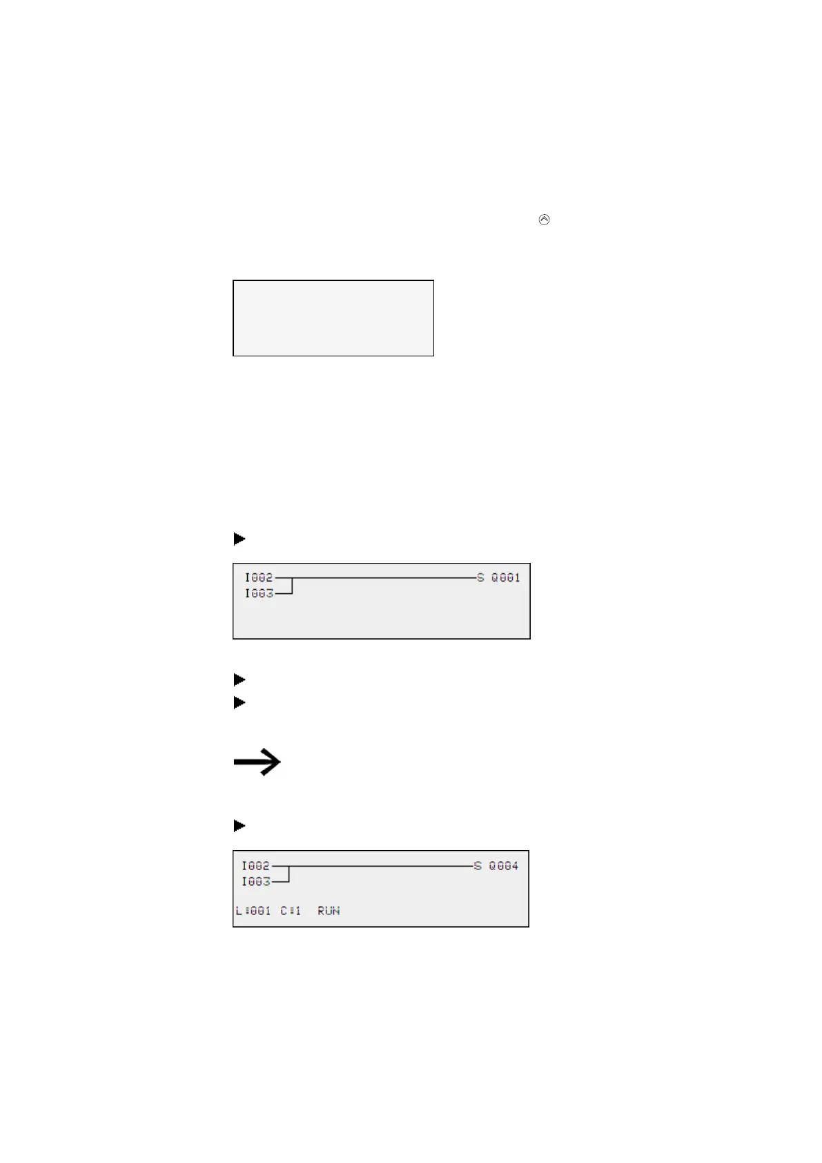
Create the small parallel circuit below and save it.
Fig. 115: Paralleling link
Switch easyE4 to RUN mode via the main menu.
Switch back to the circuit diagram display.
You are now unable to edit the circuit diagram.
If you change to the circuit diagram display but cannot
change a circuit diagram, first check whether the easyE4
device is in STOP mode.
Switch on I3.
Fig. 116: Power flow display
In the power flow display, energized connections are thicker than non-energized con-
nections.
You can follow energized connections across all rungs by scrolling the display up
and down.
206
easyE402/24 MN050009ENEaton.com