2. Installation
2.4 Connection terminals
2.4.5 Connecting analog inputs
Only possible on base devices.
Base devices with DC and UC voltage can read analog voltages within a range of 0 to
10 V via inputs I5, I6, I7, and I8 on the EASY-E4-... base device. The analog inputs'
input impedance is 13.3 kΩ.
The signal has a 12 bit resolution, value range 0 - 4 095.
The following applies:
l
I5 = IA01
l
I6 = IA02
l
I7 = IA03
l
I8 = IA04
The analog voltage inputs can also be used as digital inputs.
24 V DC
0 V
12, 24 V DC
DC:
UC:
0 V+24 V
I8I7I6I5
IA1
IA2
EASY-E4-DC-12TC1(P)
EASY-E4-DC-12TCX1(P)
IA3
IA4
F1 > 1 A
+10 V
0 - 10 V
0 V+UC
I8I7I6I5
IA
1
IA2
EASY-E4-UC-12RC1(P)
EASY-E4-UC-12RCX1(P)
IA3
IA4
F1 > 1 A
+10 V
0 - 10 V
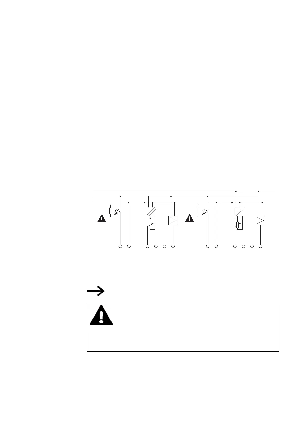
Fig. 22: Connecting the analog inputs on base devices
SETPOINT encoder:
Use a potentiometer with a resistance ≤ 1 kΩ, e.g., 1 kΩ, 0.25 W.
DANGER
Analog signals are more sensitive to interference than digital signals.
Consequently, greater care must be taken when laying and con-
necting the signal lines. The measures described below must be
adhered to in order to prevent any deviations in analog values. An
incorrect connection can lead to unwanted switching states.
In order to prevent fluctuating analog values, you should take the measures specified
for Engineering → Section "Analog signals", page 50
74
easyE402/24 MN050009ENEaton.com