6. Function blocks
6.1 Manufacturer function blocks
Other
Signal diagrams
1
2
......... .........
3
4
6
7
8
9
10
11
A B C D E F
5
. . . . . . .
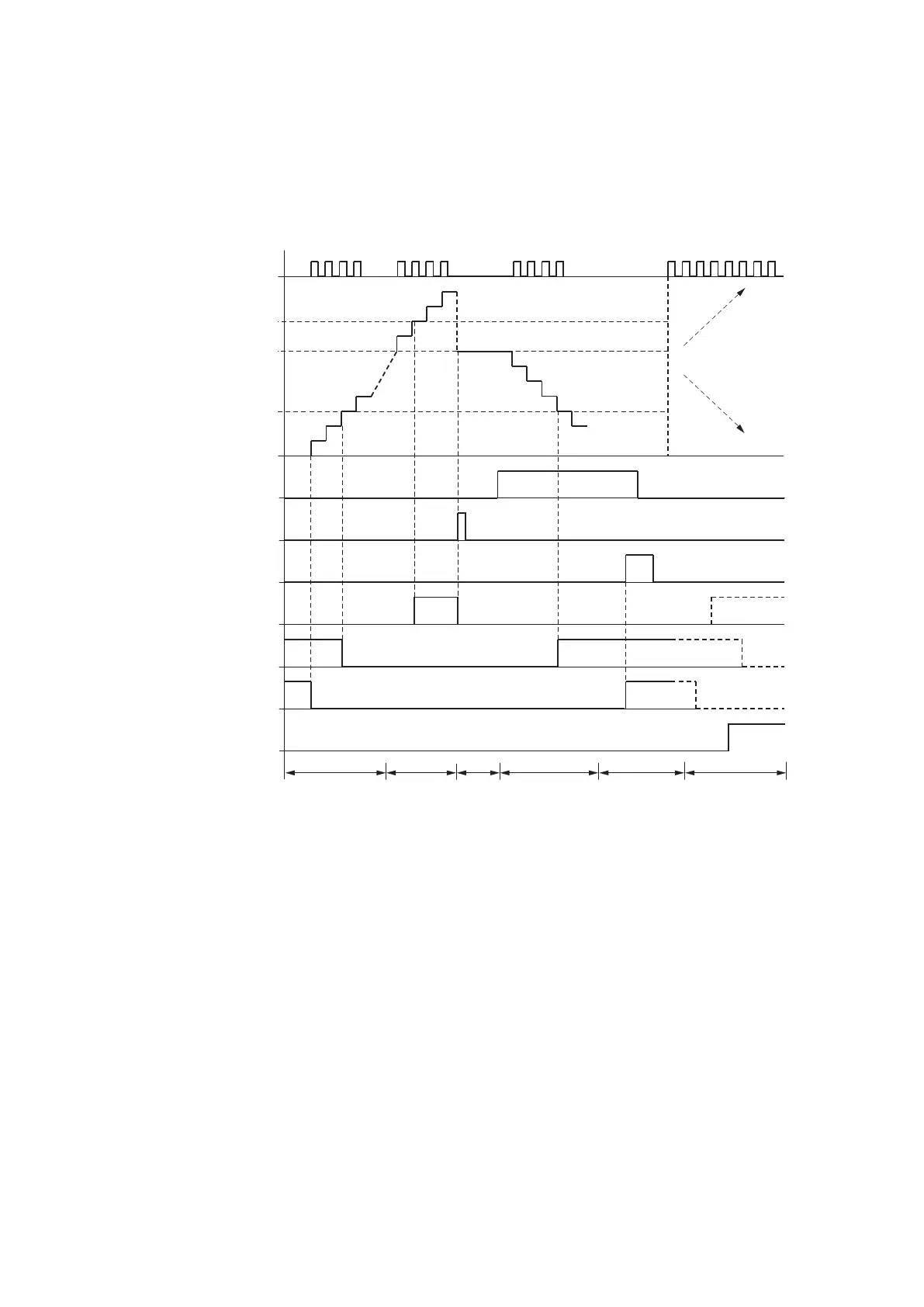
Fig. 171: Signal diagram of counter relay
Legend for Figure
1: Counter input C..C_
2: Upper threshold value SH
3: Start value SV
4: Lower threshold value SL.
5: Counting direction, coil C..D
6: Transfer start value, coil C..SE.
7: Reset coil C..RE
8: Contact (N/O) C..OF: Upper limit threshold reached or exceeded.
9: Contact (N/O) C..FB: Lower threshold value reached or undershot.
10: C..ZE = 1, if actual value is zero
11: C..CY = 1, if the value is out of range.
308
easyE402/24 MN050009ENEaton.com
 Loading...


