6. Function blocks
6.1 Manufacturer function blocks
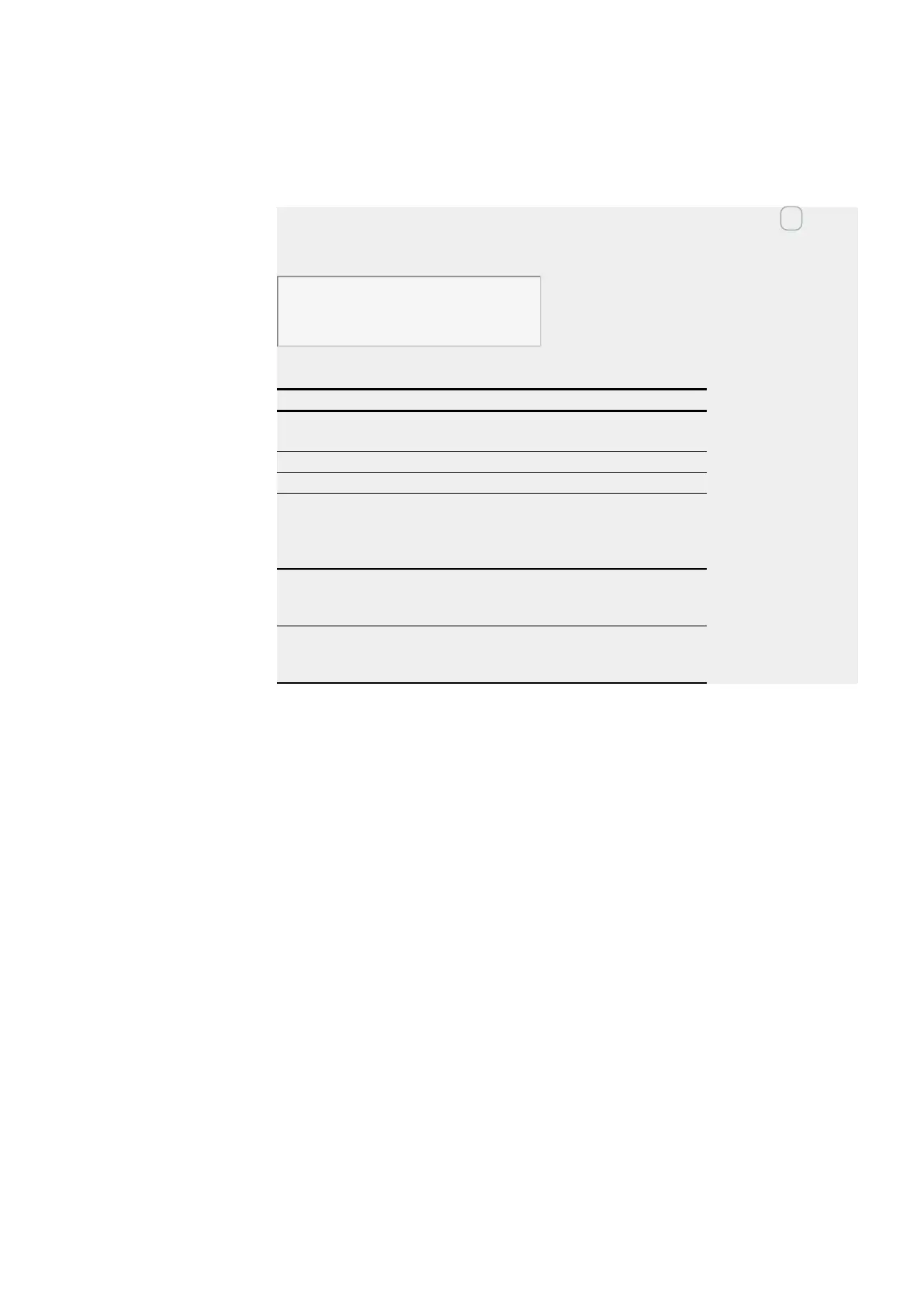
Example of an AR configuration on a device display
When using the function block in the circuit diagram for the first time, use OK to auto-
matically enter the display of function blocks on the device display, as shown in the
following figure.
AR04 ADD +
>I1
>I2
QV>
Fig. 180: Parameters on the device display
Enter the function block settings here. The display contains the following elements:
AR04 arithmetic
function block
Function block:Arithmetic
ADD +
Mode:Adder
+
Parameter set can be called via the PARAMETERS menu
>I1
First value is associated with the value at I2 via the arith-
metic operation.
Integer value range:
-2,147,483,648 to +2,147,483,647
>I2
Second value;
Integer value range:
-2,147,483,648 to +2,147,483,647
>QV
Supplies the calculation result.
Integer value range:
-2,147,483,648 to +2,147,483,647
See also
→ Section "A - Analog value comparator", page 329
→ Section "AV - Average", page 340
→ Section "CP – Comparator", page 349
→ Section "LS - Value scaling", page 353
→ Section "MM - Min-/Max function", page 358
→ Section "PM - Performance map ", page 361
→ Section "PW - Pulse width modulation", page 367
easyE402/24 MN050009ENEaton.com
339