6. Function blocks
6.1 Manufacturer function blocks
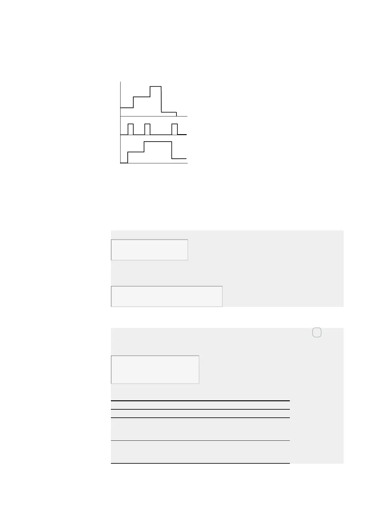
Signal diagram
Fig. 213: Signal diagram of data function block
Legend for Figure
1: Value at input DB..>I1
2: Trigger coil DB…T_
3: Value on DB…QV>
Example of a data function block with programming method EDP
The trigger coil is addressed via the network.
GT01Q1-------------------------Ä DB16T
Fig. 214: Wiring the trigger coil
The output of the data function block DB16Q1 is assigned to the input D02 EN of the
text display function block.
DB16Q1-------------------------Ä D 02EN
Fig. 215: Wiring of the function block contact
Example of a DB configuration on a device display
When using the function block in the circuit diagram for the first time, use OK to auto-
matically enter the display of function blocks on the device display, as shown in the
following figure.
DB16 +
>I1
QV>
Fig. 216: Parameters on the display
Enter the function block settings here. The display contains the following elements:
DB16 data function block
Function block: Data function block, number 16
+
Parameter set can be called via the PARAMETERS menu
>I1
Input value
Integer value range:
-2,147,483,648 to +2,147,483,647
>I2
Outputs the value of DB..I1 when triggered.
Integer value range:
-2,147,483,648 to +2,147,483,647
easyE402/24 MN050009ENEaton.com
427