6. Function blocks
6.1 Manufacturer function blocks
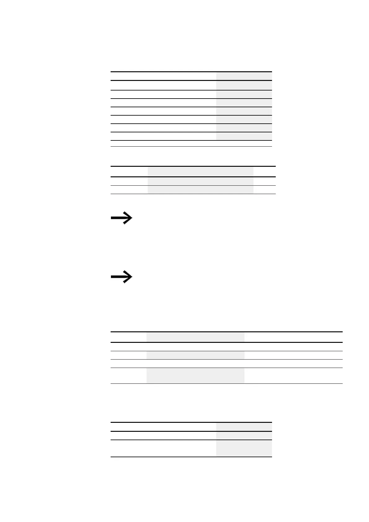
Operands Bit inputs
nN - NET marker bit
2)
NET station n
x
ID: Diagnostic alarm
x
LE - Output backlight
x
P device buttons
x
I - Bit input
x
Q - Bit output
x
Q - Bit output of a FB
x
2)
Only on projects with ≥ 2 base devices on NET
Operating modes
Description Note
BIT
Marker bit shift operation
DW
Marker double word shift operation
The factory setting of this parameter is BIT.
The operating mode is determined by selecting different
function blocks:
SR - shift register (BIT) or
SR - shift register (DWORD)
and not with the parameters for the function block as is
usually the case.
If the BIT operating mode is selected, the inputs I1, I2
and outputs D1-D8 are displayed. They have no function
in BIT mode! If they are assigned operands, these will
have no effect. The wiring of the SR function block (BIT)
is carried out in the circuit diagram.
Function block outputs
Description Note
(bit)
Q1…Q8
Output of the bit register fields 1 - 8
(DWord)
D1…D8
Register values for the shift register 1 through
8
Integer value range:
-2,147,483,648 to +2,147,483,647
Assigning operands
You can assign the following operands to the function block outputs that are numeric
outputs:
Assigning operands Value outputs
MB, MD, MW – Markers
x
NB, NW, ND – NET markers
2)
NET station n
x
easyE402/24 MN050009ENEaton.com
443