2. Installation
2.4 Connection terminals
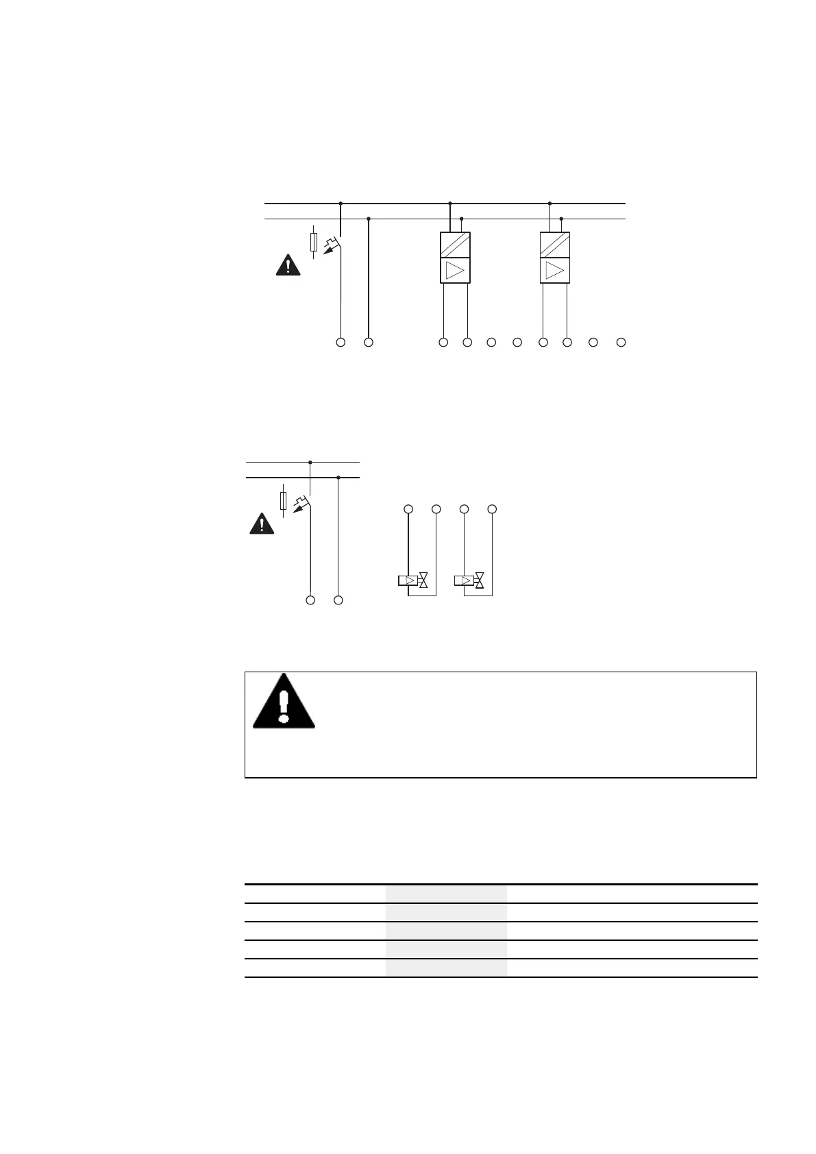
F1 > 1 A
0 V+ 24 V
IA1
IA2
EASY-E4-DC-6AE1(P)
IA3
IA4GND GND GND GND
0 - 10 V
4 - 20 mA
0 - 20 mA
0 - 10 V
4 - 20 mA
0 - 20 mA
24 V DCDC:
0 V
Fig. 28: Connecting analog inputs EASY-E4-DC-6AE1(P)
0 V+ 24 V
QA1
QA2
EASY-E4-DC-6AE1(P)
GND
GND
0 - 10 V
4 - 20 mA
0 - 20 mA
0 - 10 V
4 - 20 mA
0 - 20 mA
+24 V DC
0 V
F1 > 1 A
Fig. 29: Connecting analog outputs EASY-E4-DC-6AE1(P)
DANGER
Analog signals are more sensitive to interference than digital signals,
which is why the signal cables should be carefully routed and con-
nected.
An incorrect connection can lead to unwanted switching states.
In order to prevent fluctuating analog values, you should take the measures specified
for Engineering → Section "Analog signals", page 50
In addition to the specifications in the data sheet, the following applies to EASY-E4-
DC-6AE1(P):
Input impedance
Voltage:
12,122 kΩ
Current:
≤ 300 Ω
Voltage output:
Max. current:
10 mA (load resistance ≥1000 Ω)
Current output:
Load resistance
≤ 600 Ω
easyE402/24 MN050009ENEaton.com
79